
Introduction
Rules of our Blackjack
High-Level Design
Specific Details
What we would do differently next time
Our code: macro.inc
game1.asm (using UART for input and output)
game2.asm (using pushbuttons for input)
In this project we created a video blackjack machine using AT90S8535. In our previous labs we have gained familiarity with the 8-bit AVR microcontroller and the UART interface to transmit to and receive from a terminal. Our blackjack machine outputs text to the terminal through the UART, and at the same time accepts input from the user through push buttons. The core of our program is a random number generator which uses a 16-bit shift register and a primitive polynomial modulo 2.
Our rules of blackjack in this machine
The player attempts to beat the dealer (the computer) by obtaining a hand total that is equal to or less than 21 so that his/her total is higher than the dealerís. Each card has the same value as its index except for the aces and the picture cards. All pictures cards are counted as 10, while aces can be counted as 11 or 1, depending on the playerís choice. At the beginning of the game, the player is first dealt two cards in sequence and the dealer receives two cards, one face up and one face down. The player then has the choice to stand (no more card), to hit (wants one more card), or to double down. Doubling down means the player want to double the amount of his initial bet and receives only one additional card only. After the third card, the player can only stand or hit. This continues until either the player is busted (his/her hand exceeds a total of twenty one) or the player stands. After this, the dealer exposes his first unexposed card and draws card until he/she has a total or 17 or above. The player wins if his hand is not busted and is greater than the dealerís.
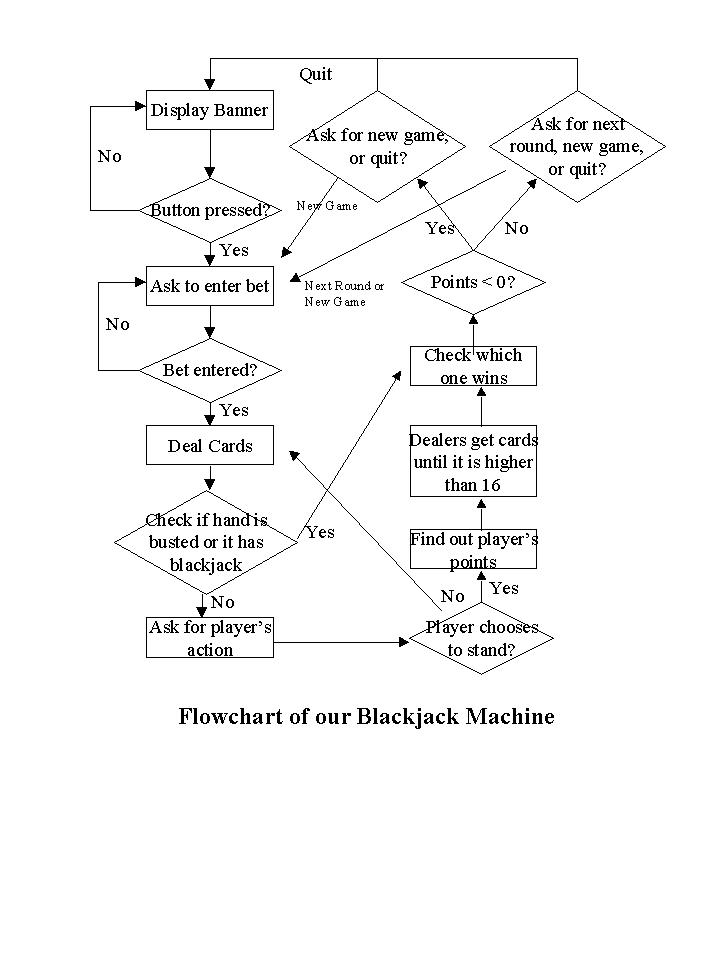
Our blackjack machine is in fact a state machine. The algorithm of our machine is as follows:
Here is the state diagram of our machine:

Random number generator
Our method for generating random numbers is to perform bit-wise operations in a 16-bit register (or two 8-bit registers since there are only 8 bit registers in the AT90S8535 microprocessor. We generate 8 random bits to obtain a random number. The theory of generating random bits is based on primitive polynomials modulo 2. Each primitive polynomial modulo 2 of order n defines a recurrence relation for obtaining a new random bit from the n preceding ones. It guarantees to generate 2n Ė 1 random bits before the sequence bits. In our sixteen-bit case, we are able to generate 215 Ė 1 (32767) bits in each cycle. We use the following primitive polynomial in our machine:
This equation tells us how to generate the new bit from the 16 bit register. Let the bits be numbered starting b0 from the right to b15 at the very left. The new bit is simply b15 ^ b1 ^ b0. The old contents of the register is shifted to the left once and then this new bit is added to becomes b0. This operation is performed eight times to get a new word (8 bits). Procedure get_random performs the above operations.
Furthermore, get_random produces 10 different cards at a time. After it has got a random 8 bit number, it converts to a number ranged from 0-51 using the mod operation, and each number corresponds to a card. Each time a card is generated, the procedure will check with previous card values to ensure that cards are not duplicated. If the card is duplicated, the program will keep generating cards until they do not have identical values.
We first need an initial value (seed) to put into this 16-bit register. Our implementation of this game forces this seed to be different every time a new game is started. We first define an arbitrary value in the 16-bit register; however, when the program is waiting for the user to press "new game" to start a new game, inside the wait loop, the value in the 16-bit register keeps decrementing until the player pushes the button. This way we can ensure that a different set of cards will be dealt when a new game starts.
Hardware (Push buttons and LEDs)
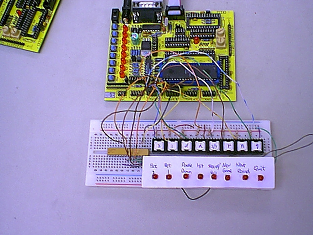
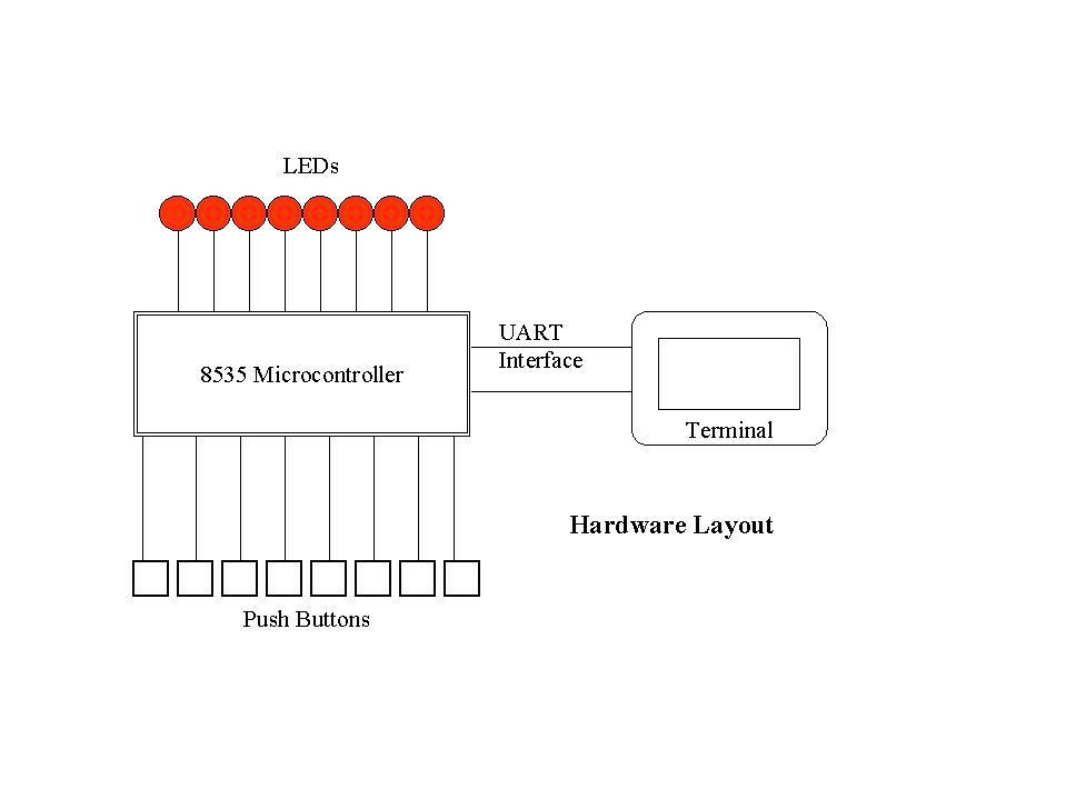
Our project requires minimal hardware. In fact our initial machine involves no extra hardware at all since we make the full use of the UART interface to accept input from the keyboard and to output text to a computer terminal. Nevertheless, it now uses the push buttons to accept inputs. There are eight push buttons in our machine. Since during each userís input selection, only a few buttons are valid. There are LEDs next to the buttons to show which ones are the valid inputs. Below shows a schematic of our hardware:

Output
Our user interface is text-based since it uses serial I/O UART. Since
itís only text based, we can only show the cards by numbers and letters.
Here is our notation:
| A
T J Q K |
Ace
Ten Jack Queen King |
D
C H S |
Diamonds
Clubs Hearts Spades |
TS QH AS 6C 9D
The code involving UART is very simple. It is the same as the one we used in lab 4.
What we would do differently next time
While building this blackjack machine, we encountered few serious problems at the beginning with our code. For example, our cards generated were not random at all, and there were a lot of problems with the output of text messages through the UART interfaces. Nevertheless, these bugs were eliminated through our thorough inspection of our codes, and through simulating in AVR Studio. We have spent a substantial amount of time in debugging, and therefore, what we would do differently next time is to change our way of writing codes, and debugging. In the first two weeks of our project, we wrote our code for the whole game without testing them, and in the last week we encountered a lot of problems since the code was not working as expected. And we had no idea how to tackle the problems initially since the code is so big. Therefore, next time, we would write small pieces of code one by one, thoroughly test them pieces by pieces before merging into one big program.
Furthermore, since we output to a terminal through UART, our product is not portable at all. We would like to make it more portable next time. We looked at the catalog, and we could not find a good and inexpensive LCD. We do not use the LCD we used in Labs 5 & 6 for display because the 16-character limit is too restrictive. There is a 2-line LCD in the catalog; however, this 2-line limit is also restrictive in our opinion and we thus use the terminal for display. Next time we would like to use a color, bit-mapped LCD. We would not display the numbers and suits of the cards, but instead images of real cards. It would take us a lot of time, but only with this kind of display could we make our project more like a real product sold in market.
Copyright 1999. Kenneth Kwok and Andy Leung