.S.P.A.R.C.
Self Propelled Autonomous Robotic Cricket
[Updated May 12, 2000]
[Journal]
...notes are listed in FIFO format... details regarding code and hardware design are in their respective sub-chapters...
April 17th : Inspired by Sony's AIBO robotic dog, I decided to make (from scratch) a robotic pet. After much thinking on what to build, I gathered up code from a previous lab, Cricket Chirping, to create what I call .S.P.A.R.C.
April 18th : After seeing what could be involved in the project I set out to accomplish several key goals to which, if I had time, would add too. There were 4 goals that I wanted to achieve : 1) Walking 2) Chirping 3) Some sort of behavioral motion control... like running away from people. 4) Jumping?!?
April 19th : Started coding the necessary assembly for servo control. At this point while coding I realize that (from reading about servo controllers) I need to get my servos and test what pulse width modulation (PWM) they need to turn. It seems that every manufacturer uses their own PWM burst. I went to the local Ithaca electronic shops and looked for servos. Not to my surprise, it is hard getting 6 decent (high-torque, small, light) servos in the boonies. I decide to call it a day after sitting in this lab for 3 hours.
April 20th : The first thing to do on my agenda today is order those servos online. As a childhood radio control freak, I remember Tower Hobbies. Cool, they are still around and bigger than ever. What do you know, a special on bulk servos!!! *ack* They are still $50 for 6 TS-53 standard servos...eh what the heck, only the best for my pet. Fed-Ex Next Day Air... $25 extra? Why not... I decide to do other work as I wait for my servos to come in Monday, being that the lab is closed.
April 21st : Good news and bad news... Bad news is that my shipment seems to have been delayd another day!! *sigh* Running out of time!! Good news? I called Tower Hobbies up and they refunded my shipping!! "Saved" myself $25 on shipping (plus NO tax to begin with...) What a steal. I decide to work on my servo control as I can always change my code later to reflect any PWM requirements. Without knowing by hardware testing, I conceed and say that I am done with the walking code. I will start on the Chirping code next.
April 24th : Got my servos... nice servos but a little bigger than I thought they would be but nevertheless they HAVE to do for now. I put the chirping code on hold and I wire up the servos to PortC and the power supply. Err...servos are not moving. After checking (with a voltmeter) if they are getting power and a control signal, they are still not moving. After consulting with the TA, who did his best to help me out, I couldn't find why the servo motors weren't moving. I scour the Internet for some help... no luck! *grrr* So I decide to bite the bullet and do some brute force coding to force the servos to move. After 2 hours of tweaking and debugging, I am giving up for today... *sigh*
April 25th : After thinking about the code, I realize my error... the servos were not getting the PWM signal fast enough to actually get them moving. *twitch twitch* The servos now move but not in a smooth linear fashion that I hoped for. After debugging again for the remaining lab period (time flies when you are tweaking code) I call it a day.
April 26th : I didn't go to lab today... why? Cause I didn't feel like it.
April 27th : Another rainy weekday. I decide to get the chirping code started and completed by next Monday as time is running short. Using the code from a previous lab, I get the chirping code to work. *woo hoo* What a boost from the demoralizing servo debugging. I try to get the servos to "walk" but again no luck.
April 28th : I am really getting nervous as the deadline is approaching and I have ABSOLUTELY nothing to show for it except a cricket that chirps and twitches its legs... hmm... should I rename the project? I am honestly thinking to demo the robot and say that someone stepped on it beforehand (i.e. dead cricket - do dead crickets chirp though?? Hmmm...). Then I remembered... extension! Demos are due not next week but the week after... I betetr get this sucker moving or else I won't be happy... *sigh* TGIF... off to sleep. :)
May 1st : I sit in lab looking at the six servos and decide to restart the code for the walking... 2 hours later... *TA DA*.. I cheer at the sight of 6 whining servos WALKING!! No time for excitement though as I have to YET to build the cricket's body with all the wiring and protoboards... After tweaking and trying to combine the chirping code and walking code I call it a day (again disgruntled at how fast time moves...).
May 3rd : Don't ask about yesterday, I'll just remind you how much I hate prelims. Anyway back to my little AIBO wannabe... After several attempts to combine the code I realize that there just isn't any time to deal with little annoying bugs. I decide to use two Atmel 8515's : one for chirping and one for walking. Of course this will also let me add to either chip, any extras that I wish I had time for. Cool... now I have to figure out how to power S.P.A.R.C. and all the schematics for getting it up and running minus the DC power supply... I'll take care of that tomorrow.
May 4th : After spending $45 at Radio Shack on basic stuff - protoboards, capacitors, resistors, batteries.... etc. I realize... my cricket is gonna be one FAT insect. What to do... it turns out that either I have to invent some super light battery that will power the whole thing or I gotta cut corners somewhere. To my disappointment I cut off two legs. Reorganizing the code wasn't hard at all and I even thought of a feature that would meet my third goal of some behavior. I decided to make the cricket run and stop chirping if it detects light...other wise chirp and walk around (aimlessly at this point because I don't think I'll have time to get the infrared object sensor completed and working). I got the servos to run and walk depending on a button push on the Atmel board... so I guess I will create a circuit to put it all together.
May 5th : Started to build the body and attach the servos... I also started to solder up my cricket's "brain" board. ARGH!!! I wired up one of the servo motors wrong and I broke it. Damn... To all those aspiring to become an engineer... take note that black smoke accompanied by a pungent (eye-burning) plastic odor is ALWAYS a bad sign. Thank God I had those two extra servos. Replaced the "broken" leg with another. I am having trouble designing the circuit for to turn off the chirping chip and to force the cricket to run. I will look into it over the weekend.
May 8th : Damn!!! 3 of the four servos on the cricket have died!!! I knew I should have gotten metal ball bearings (BB) for the motors... The plastic BB's, under the weight of the body and constant testing from day one, have taken their toll and snapped. I am ordering new ones now... I am running out of time!!! Sheesh... I have finals too... Joy. I will continue to finish up creating the body of the cricket...which at this point looks like a lunch box with four legs. Don't laugh :)
May 9th : Power requirements are STEEP... I am now using 4Alkaline/Lithium 9V batteries to power the servos, and a R/C 9.6V extended life battery to power everything else. My cricket is one hungry insect... I am considering naming this guy Cockroach instead of Cricket. Servo bearings did not come yet... still waiting. In the meantime, I am trying to get my IR sensors to work... things look very BLEEK at this point for them... I have soldered them on just incase I get the code working.
May 11th : Still no sign of those damn bearings. I have finished up wiring the power stuff and am now just waiting for the bearings to come so I can attach the legs. Man, this things is gonna be one ugly mother... I can't wait to snap some pics to show you...
May 12th : Gosh I hate finals... Called Tower Hobbies and they said next MONDAY... *sigh* OK there goes my cricket project.... dead cricket because of mechnical problems... I have to see what happens next with Professor Land... PLEASE GOD... let my cricket LIVE!!!!!
May 13th : Weekend... I prepared for the arrival for the bearings. I completed soldering in everything on the board and attached the Q-Tip legs. I used Q-Tips because it was easy to implement and the cotton swabs seemed to provide adequate friction for the cricket to move on the kitchen floor where I was testing.
May 14th : Looking over the cricket, I decided to cut more weight off it. Details are described below but essentially I rewired the power lines and ended up tossing the heavy 9.6V R/C car battery.
May 15th : Servo bearings arrived... without the Atmel chips and 4MHz Xtals, I cannot test the new final design yet... Emailed professor... hope everything goes well.
May 16th : Morning.. Demo @ 3PM. Finally... cricket is ready. (But of course, the cricket is late... *sigh* bad news...).
[Introduction]
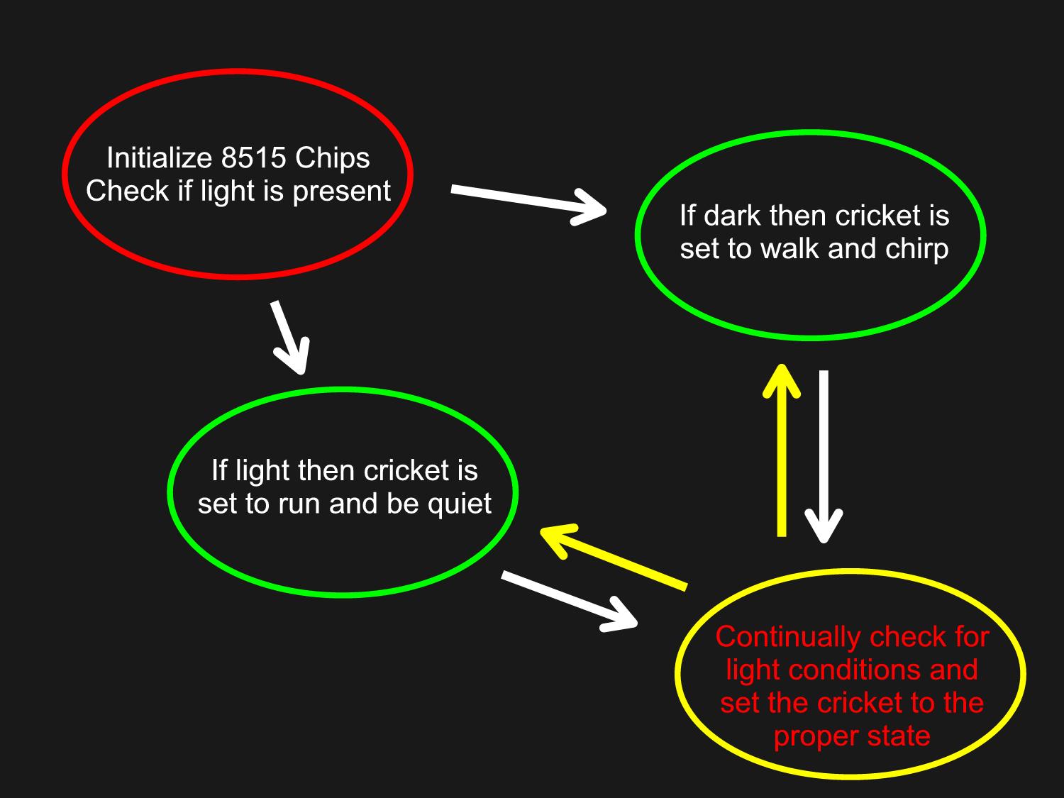
For my final project in EE 476 I have decided to make S.P.A.R.C. - a Self Propelled Autonomous Robotic Cricket. It is inspired by Sony's AIBO robotic dog but S.P.A.R.C. is obviously a much more primitive robotic pet. It is a self contained robot with no user intervention involved except for turning it off and on via disconnecting the batteries. S.P.A.R.C.'s final design should walk and chirp if there is no light present and run and stay quiet if there is light present, which is somewhat similar to a real cricket in nature. I hoped that designing S.P.A.R.C. that I would get better insight into how robots work and actually to see if I could make something of this caliber in 3 weeks.
[High Level Design]
There were several aspects to the design in both hardware and software. Basically, due to unforseen delays in the genesis of S.P.A.R.C., I have decided to use two Atmel AT90S8515 chips : one for motion control (servos) and one for chirping. As a possible bonus, in the future, by using this two chip design, I will have the necessary resources (such as more memory and registers) to possibly add more fuctions to S.P.A.R.C. I initially set out to also have software based light detection. Due to time contraints, however, I have created the analogous hardware representation of what I wanted the software to do.
Since S.P.A.R.C. is not a learning robot, it was easier for me to create him. A memory-less design would allow me to concentrate on actually building the cricket faster because less coding was needed. Here is a logistical flow diagram of how S.P.A.R.C. works:
Figure 1.
[Software/Hardware Design]
Software:
Chip one - motion control.... The fundamental design of S.P.A.R.C. was to create a walking robot using four standard servos. To actuate the servos in a linear motion, there was need to supply positive PWM pulses into it. The rate at which pulses are sent to the servo was set at 10 milliseconds. A pulse width of 1.5 milliseconds positions the servo at its center, while 1 millisecond and 2 milliseconds were the accepted limits to either side, gave the servo that movement. To supply this pulse, I used the 8515's Timer 1 to generate a PWM every 10 millisecond. Timer 0 was used to create the position time. In my case, I used a shorter positioning pulse because it took too long for the servo to go all the way from left to right. To do this I sent the servos about a 1.65 millisecond and a 1.35 millisecond position pulse every 10 milliseconds. This would allow for quick movement so there was no servo motion lag. The signals were modified then to reflect the "walk" and the "run", which is basically controlled by the input of my light detection circuit on Port B. Once it detects a signal on any of the pins, the software jumps into its respective loop where it will send PWM signals faster or slower depending on a "walk" or "run" situation.
Chip two - chirping... To chirp, a speaker was hardwired to another Atmel 8515 chip. Similar to the motion control, the premise behind making noise was to turn off and turn on the port bits to the desired noise frequency. This was achieved using Timer 1 compare and Timer 0. As stated before, I used old code from a previous laboratory assignment but it is a very stripped down version, where there is no user input and it only outputs one type of chirp. There is no logic in the code to handle to check if there is light as this was handled in hardware only.
Hardware:
The basic brains of S.P.A.R.C. is in the code of the two Atmel chips, which by the way are NOT connected in anyway. Running them independently saved time and I didn't have to deal with setting up any protocols for the two chips to talk to each other. The only thing that they do share is the light detection circuit.
There were several ways to implement the light detection circuit... using a solar panel to activate a relay to output the required signals or use a photo resistor. I opted to choose the photo resistor only because solar panels were too delicate to handle and required a voltage booster. The schematic, in Figure 2, shows how the detection circuit works... Basically, when there is NO light present, the relay is on and there is power supplied to the second Atmel chip (which makes the noise) and the signal to the first 8515 (servo control) is high @ 5V, which the software detects and sets the servos to "walk". Upon light detection, the circuit fires up and deactivates the relay, which turns off the second Atmel chip, which in turn makes my cricket shut up...also the signal to the first chip's Port B5 pin is set to 0V which the software detects and sets the servos to a "run" situation.
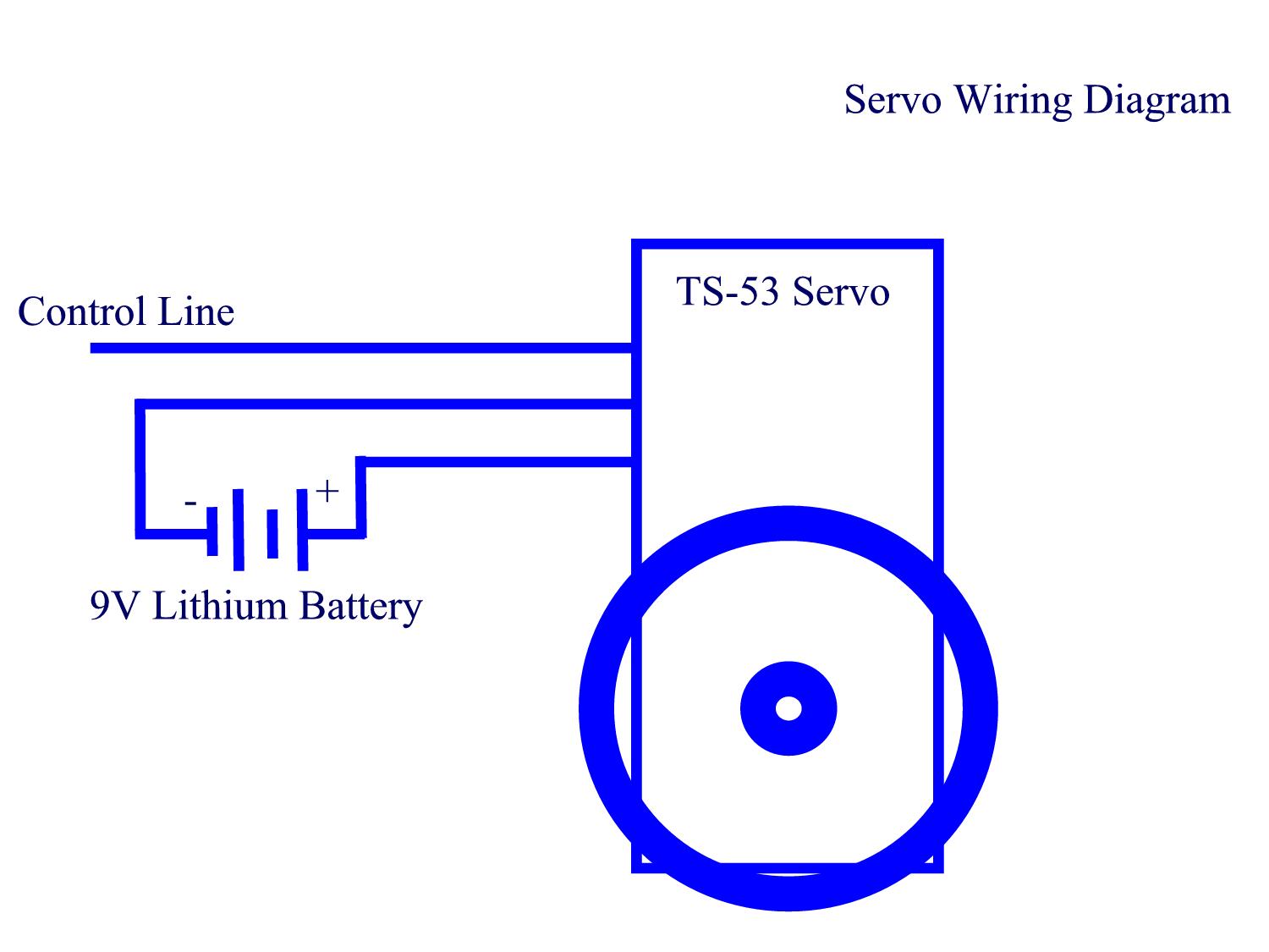
The servos consist of a motor, potentiometer, gears and three wires - red, black and white. Red and black represent power and ground respectively, while the white wire is used for the PWM control signal. Since the software was used to control the PWM signal, there was no real hardware setup except for making the appropriate connections. I must add that in my design, the servos are constantly moving to keep the servos "alive". Servos, inherent in their design, are optimized for low power consumption, so if there is no signal after getting to the correct position, they will shut off and be "dead". Dead servos are susceptible to external forces and won't hold their position if touched. This posed a problem for me as the weight of the body would definately make the cricket collapse if the servos weren't active. I addressed this problem by leaving the servos on all the time but this created another problem... power consumption. I originally wired all four servos to one R/C 9.6V battery but this proved to be futile. The servos would only actuate for about 5 minutes before sucking the battery dry. I then opted to give each servo their own 9V battery so that I can replace the power as needed. This proved to be too heavy as well, so I finally ended up making two servos share a single 9V battery. To further reduce weight, I also used Lithium based 9V batteries, which gave the servos a lot more life and reducing weight, but at $3 a pop, this design is definately not cheap.
The chips were originally powered by the 9.6V R/C battery that was originally designed for the servos. With already the cricket weighed down by two 9V batteries, the addition of the R/C car battery made the legs collapse. I decided to use a third 9V Lithium battery, running through a 5V regulator, to power the Atmel chip for servo control. Note that to power the second chirping chip, the power first goes through the light detection circuit to see if there should be noise or not...and then activates as necessary.
Upon closer inspection of the cricket itself, you will notice an IR emitter, an IR collector and a 556 timing chip. Well, added for the future, this circuit was to feed any of the two Atmel chips (didn't matter which one - depends on how hard it was to integrate the code) a signal so that my cricket would know if there was something in the way of it. Similar to a motion detector, the IR transmitter would beam out a signal and the collector would then see how fast (or slow) it took for any reflection to come back (if there was any at all). The code for this was never completed but is still in the works... if I could get my hands on an Atmel starter kit, I would most definately put this feature in. But for now, it's just there with the future in mind... poor blind little cricket.
Figure 3 shows the wiring diagram to the servos.
Figure 2
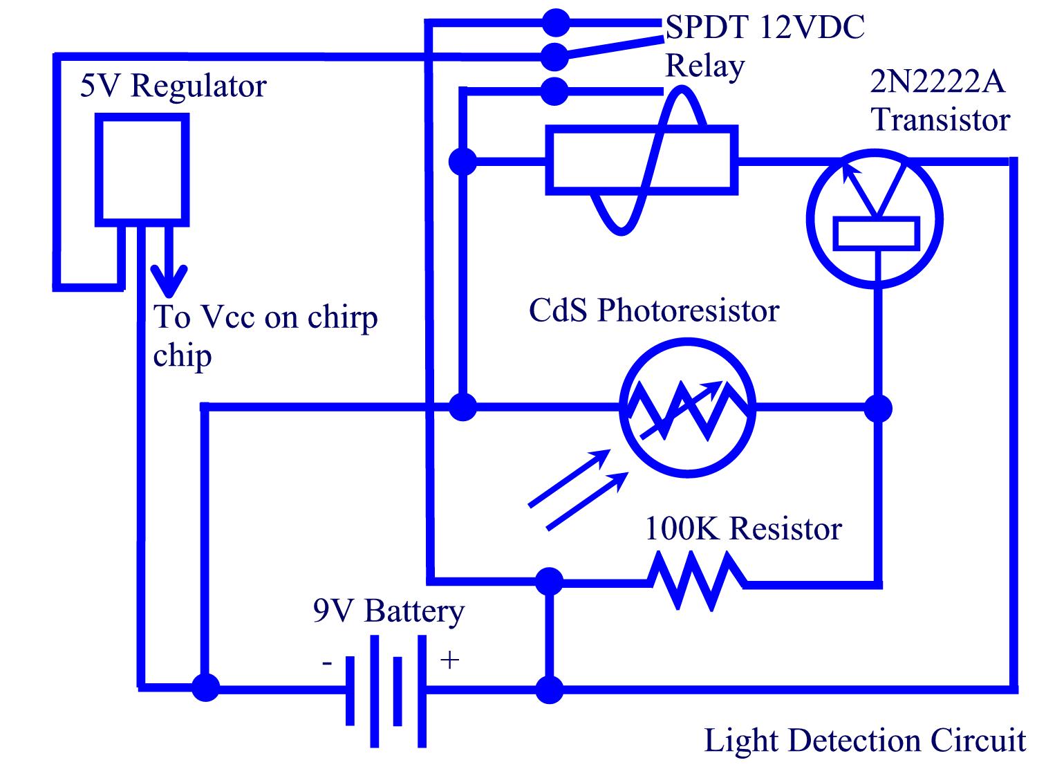
Figure 3
[Results]
Well as you may know from my journal, the cricket is somewhat non-functional. Only one out of the four legs work because of mechanical problems BUT before this disaster, the cricket was working as designed (minus all the neat little extras that I was hoping to get to) on the Atmel starter kit boards... The light detection circuit is too sensitive for the moment but can be easily remidied if I replace the photo resistor with another less reactive one. All in all, the cricket (or the mini-lunchbox with legs as my friends call it) works perfectly... running when there's light and walking/chirping when there isn't.
As soon as I demo, I will update this portion of the project... stay tuned.
Click here to download all the source code for this project.
[Conclusions]
This project was definately biased toward hardware design for me as I am a computer science major and not EE... the coding was annoyingly hard to debug but I realized my mistakes. Hardware on the other hand wasn't that hard to do except for the designing portion. Getting the right voltages and thinking of how to implement circuits was a new challenge for me and can be seen in my cricket's vast array of functionality (or LACK thereof). I would definately not partake in such a tedious project next time as there was very little help in the software aspect and little help in simple robotics. If I had more time, I would think otherwise. This was definately a learning experience as I poorly balanced the software-hardware balance that this project entailed.
I am definately going to expand on this cricket design as it has the potential to be a very cool toy... although it would be quite expensive as seen by the reciepts to Radio Shack. At the least, I spent about $150 on this robot... not too expensive but not very cheap either. Anyways, future upgrades would entail getting better servos, minimizing and optimizing the circuits so I can fit them into a body that looks like an insect, and lastly adding more features like steering, motion detection (via sonar or IR), sleep mode (where upon low battery detection, would shut off movement and emit a "low battery" chirp noise), and jumping...