Introduction
Strobe lights have always been an integral part of dance parties, adding an additional element of excitement to the festivities on hand. The combination of flashing lights and music-especially those with a definitive strong beat- are a natural complement to one another, where the strobing of light is an extension and links one's aural perception to his visual senses. The applications of strobe lights are numerous. In more involved and comprehensive applications the strobe user would like the strobe to help fuse together the music and light. For our final project we opted to attempt to create such a strobe system appropriate for the more complex application by creating a light strobe system that flashes a light source directly in sync with the music in real time. By processing an audio source through a beat detection algorithm we can effectively detect whenever there is a strong 'bassy' beat and then flash the light accordingly. The benefit of a beat-sensitive strobe system is to create a direct correlation with the music and light that enhances the music with synched flashes of light.
High Level Design
In order to detect the beat of the music, the music first needs to be thoroughly processed. Since the beat detecting strobe must be able to flash instantaneously on the beat, the beat detection algorithm operates in real-time. The idea behind the beat-detection algorithm is based upon the premise that the strong 'beats' of any sample of music are primarily composed of low frequency components. Given a low-passed audio signal, a subtle spike in the envelope waveform characterizes a strong beat in the music. Thus by monitoring the envelope of a low-passed waveform, one can detect the beats in the music. Since the 'beat spike' in the waveform envelope sometimes can be subtle and difficult to detect, we found that further differentiating and then passing the signal through a running average filter results in a waveform whose spikes in the waveform envelope accurately correlate with the beat of the music. In order to determine when exactly to flash the strobe, we compare the running average signal to a strobe signal threshold. Whenever the signal is above the strobe threshold, the system flashes the LEDs, which we used as our light source.
An outline of the beat detection algorithm is as follows:
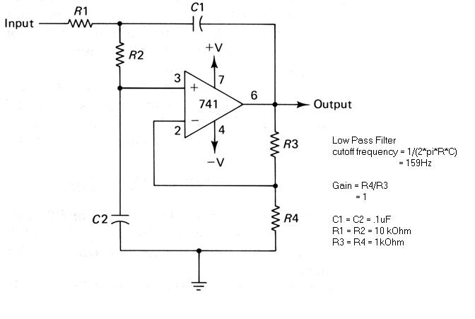
1. Pass music through low pass filter and amplify filtered signal (Figure 1)
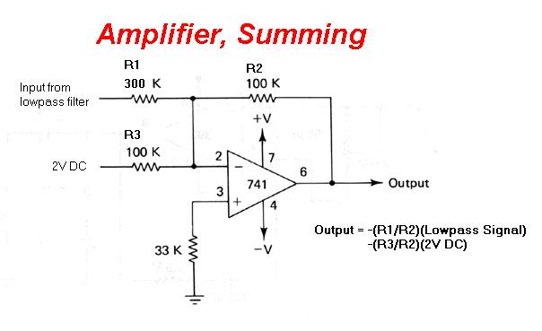
2. Add 2V DC offset to signal to elevate signal to effective range of ADC
3. Take samples of low-passed music with ADC and full wave rectify
4. Average current value with previous and take derivative and full wave rectify resulting signal
5. Pass differential signal through running average filter (later values weighted more)
6. Keep track of the maximum level of the running average and calculate threshold based on this max value (dynamic threshold)
7. Compare current sample value with threshold-if signal above threshold flash strobe
Strobe flash if sample is greater than threshold, then return to Step 1A maximum running average value is continuously monitored and updated. This value is used to calculate the strobe threshold, which is a pre-set fraction of the maximum running average.

Figure 1. Low Pass Filter with cutoff frequency 160 HzProgram/Hardware Design:Hardware:
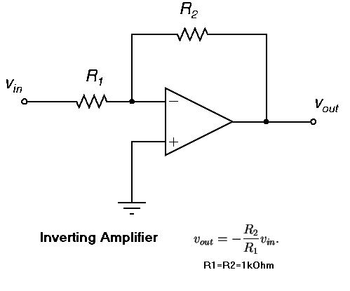
The single channel audio signal (2V pk-pk) is first fed into a two pole low-pass filter with a cut-off frequency of approximately 159Hz with unity gain (Figure 1). The cut-off frequency was selected through experimenting which frequency best preserved just the "beat" portion of the music. Since the ADC is referenced to 4.096V, it can only sample voltages between 0-4.096V. Thus a 2V DC offset is added to the low-passed signal with an inverting summing amplifier in order to raise the signal into the ADCs sampling range. In addition, the low-passed signal is amplified with a gain of 3 to increase the resolution of the sampled data. Since the output of the summing amplifier is negated, the signal is passed through an inverting amplifier with zero gain to obtain the correct sign (Figure 2).
For debugging purposes we also included an audio output tap at the output of the low-pass filter to allow us to listen to the music and observe the accuracy of the strobe to the beat of the music. In addition, we also constructed an 8-bit DAC to allow us to view the signal at various stages throughout the beat-detection algorithm. The other hardware include the 16-key keypad as well as 16 character LCD display used in previous labs. The LEDS on the STK200 were used as the strobe lights and a 8 bit DAC (the same as in previous sinewave generator lab) was constructed for monitoring each step in the algorithm used for testing.
The audio source was provided with a line out connection (mono- one channel only) to a Sony discman.
Software:
The bulk of the software is concentrated in the beat-detection algorithm. A more specific layout of the algorithm is detailed below. Since the system runs in real time, the algorithm below is completed once for every ADC sample:
1. Take sample of low-passed music with ADC and invert sample if necessary:
Since we are primarily interested in the envelope waveform, full wave rectification of the signal doubles the resolution of the envelope. Because the effective range of the DAC is from 0-4096 and the sampled signal is centered about 2048, any data below 2048 is negated.2. Smooth signal with averaging filter:
The averaging filter actually just takes the average of the current sample and the sample after Step 1 from the previous iteration, which is stored and recalled from RAM.3. Take first order derivative and invert differentiated signal if negative:
The sample is differentiated (rise/run) by assuming the run is equal to unity and just taking the difference between the current value after Step 2 with the previous value of Step 2 stored in RAM. The run is equal to unity in order to exaggerate the derivative which helps in enhancing the magnitude of the beat spikes.4. Pass differentiated signal through running average:
The running average filter equation is as follows
running average =
(old running avg)*(Coeff) + (new sample)*(1-Coeff)
We used a value of: Coeff = .975Note: Since we cannot do decimal math, we use 975 to represent .975
So our formula is: new running avg = (old running avg)*(Coeff)/1000 + (new term)*(1000 - Coeff)/1000
--basically scale by 10005. Check if sample is new maximum value, and update if necessary:
The current sample is compared with the previous running avg maximum stored in RAM. If the new sample is greater, the maximum value is updated.6. Calculate threshold from maximum value, and compare sample with threshold. Strobe flash if sample is greater than threshold, then return to Step 1:
The threshold is dynamic in the sense that it is recalculated from the maximum running avg which itself is continuously monitored. The threshold is set anywhere between .5 to .8 of the maximum value, depending on various variables such as the power source used to power the various hardware as well as the reference voltage for ADC. Thus for best beat tracking accuracy, the ideal threshold value should be adjusted whenever the voltage sources and references change. When the current value is above the threshold, the LED is lit, otherwise the LED is turned off. At this point the system returns to Step 1 to sample another value from the ADC.
Aside from the beat-detection algorithm, no other new software is introduced. The debounce and keyboard scan subroutines are taken from the previous labs.Results:
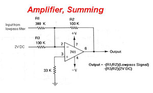
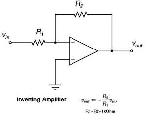
Figure 2. Summing Amplifier with gain=3 for audio input and gain=1 for DC offset and Inverting Amplifier with gain=1
Conclusion/What we would do differently next time:
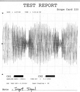
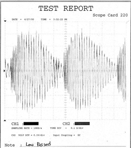
Input Signal to low pass filter Output of low pass filter
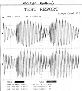
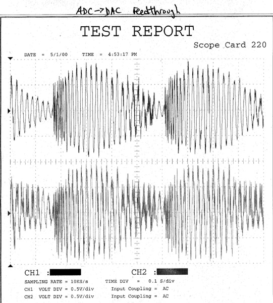
ADC to DAC direct readthrough to test ADC sampling
(Bottom waveform is input to ADC)
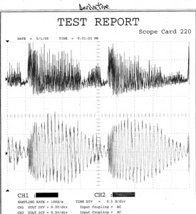
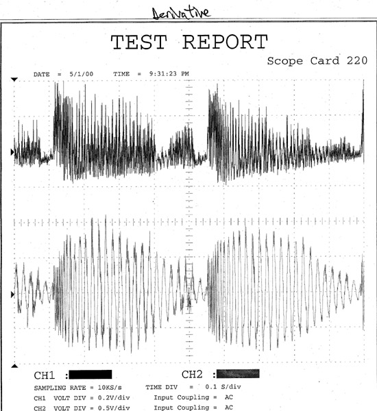
Output after rectification, smoothing and derivative performed
(Bottom waveform is input to ADC)
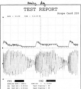
Running average of derivative
(Bottom waveform is input to ADC)

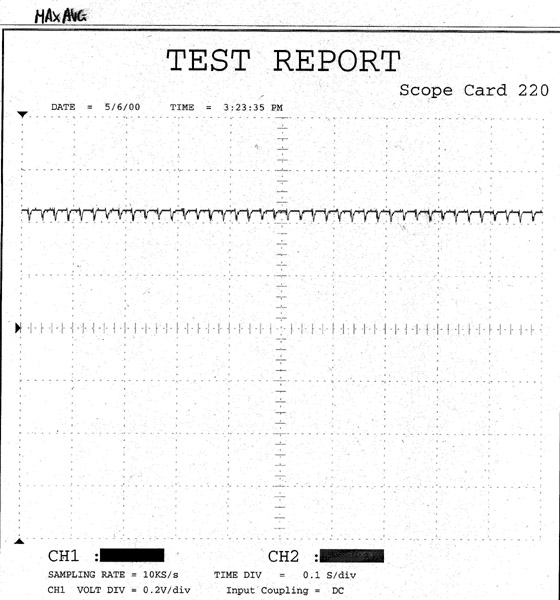
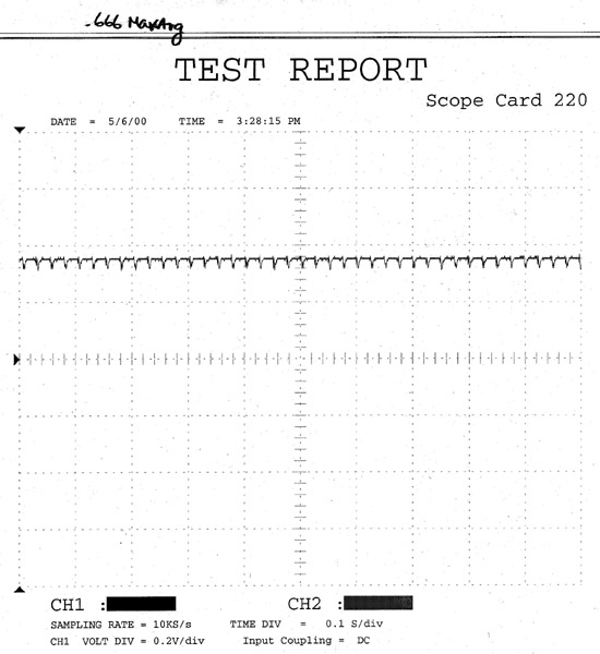
Maximum average value
(Note this is scaled for output to a DAC for measurement)
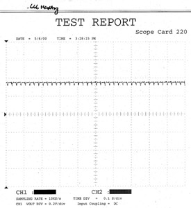

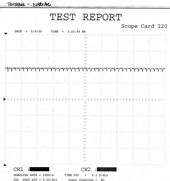
Two threshold values, calculated as a fraction of the maximum average
The beat tracker works surprisingly well given our crude beat detection algorithm. Even music with non-synchronized beats work. The lights can be observed to actually strobe with a period proportional to the intensity of the beat. In addition, the speed of the system results in no obeservable phase lag between the audio beat and the strobe flash. However there must be a sufficient amount of beat information (i.e. bass) for the system to work properly. Another factor that affects the system is the variability with the power supplies in the lab. This changes the threshold value that works the best, but this can be tweaked easily.
The algorithm can be fine tuned for better accuracy and a feature that will reset the maximum average for each song would be desirable. We tried implementing a start/stop feature too but we ran into trouble with running out of registers (overlapping registers getting "killed" during the interrupt service) because of the large number of registers required for the math functions.
Lastly, if given more time we would liked to have increased the functionality of the system by adding additional features such as a user-selectable strobe frequency mode that allows the user to manually select the strobe frequency as well as a pre-programmed beat pattern mode that allows the user to select from a library of custom beat patterns.
Overall, the project was successful and we wish that we had time to build a high power strobe and firing circuit so we could use the system at our next party.
Source Code:Main Program: code.asm
Math Subroutines: math.asm