The 8-Trak Sampler
By Robert Costanzo and Bill Stysiack

The user interface through a hyperterminal was straight forward. The user could select record, play, delete, or list from the prompt. When choosing record (by pressing 'r'), the user was then prompted for a bit resolution to record at (either 8, 4, 2, or 1) and then a freqency (either 8KHz, 4KHz, 2KHz, or 1KHz). The device then records until another command is pressed or it runs out of memory. When choosing play (by pressing 'g'), the user was shown all tracks recorded and selects the number of the track he wants to play. The user was then prompted for the frequency at which to playback (either 8, 4, 2, or 1). When pressing delete (the 'd' key), the user was again prompted with a list of all tracks and then could choose which one to delete. Finally, the list function (the 'l' key) just printed out each track as well as its starting and ending location in memory, bit resolution, and frequency.
The 8515 handled all of the complex operations. First, it communicated through the UART to a computer running hyperterminal to display all prompts and receive user input. The 32KB of external memory was accessed through Port A and Port C. The three main functions of the 8515 were: playback, recording, and deleting.
For playback, the frequency is received from the user and the 8515 sends data to the 8535 to play at that rate through the SPI on Port B. The user also selects which track to play, and the 8515 looks up the starting and ending location of that track from the 59 byte track table. It then goes to the external memory and plays from the starting memory location until it reaches the ending location at the specified frequency.
For recording, the user specifies both the frequency and the bit resolution. So the 8515 requests data from the 8535 through the SPI at the rate of the frequency and only takes the user specified number of bits from each sample. The data is then stored in the external memory at the next available track slot. Data is continually stored until the user issues another command or we run out of external memory. After recording is finished, the track table is updated with the starting and ending memory locations of the track.
The final major function of the 8515 was to remove recorded tracks. We placed a maximum of 8 tracks due to our memory limitation, so removing tracks was necessary for usability. The user selected the track number he wants removed, and first we remove the entry from the track table by invalidating the first byte (which contains the frequency and bit resolution information). We then move the next track into the deleted track's position, and move the track after that one spot up until the last track is reached. By doing this, we kept our file system simple and optimized after every write or removal. We also move the actual data stored in memory corresponding to the moved tracks to prevent our file system from becoming fragmented.
The hardware we used involved a D/A converter to drive the speaker and a circuit to power the microphone through an audio amplifier into the A/D converter on the 8535. The D/A converter consisted of a resistor pack of 10KOhm resistors and another of 20KOhms resistors. See the hardware schematics for the input circuit and output circuit for more details.
Hardware listing:
As a work-around, we attempted to implement our own communication method. This involved using two pins of PortB for output, two pins of PortB for input, and a single pin on PortB for a clock signal. The 8515 generated the clock signal internally with Timer0. We set it to run at 200KHz. This signal was then sent to the 8535 to keep the two devices synchronized. We then only allowed transfers to take place on a high clock, and only one transfer per clock period. The 8535 played the "dummy" again and constantly took 8-bit samples from its A/D converter and broke it down into 2-bit fragments to send over PortB. It also constantly read from its two input pins on PortB and constructed a 8-bit output signal to send to PortC. The 8515 not only controlled the clock signal, but also sampled to and from PortB at the user specified rate as well as at the user specified bit resolution. When not recording, the 8515 merely ignored the data being sent to it. When not playing, the 8515 continually sent zeros to the 8535.
Even though our project did not work as a whole, we did get several complex parts working on their own. The user interface worked fine. Also, we were able to sample at user specified frequencies and bit reslutions. We were able to write and read to our 32KB block of RAM. Also, our file system worked great. We were able to record tracks and delete any number of them at will. Even though we had no voice data stored in memory, we could still tell that this was functioning since the starting and ending track pointers were adjusted properly with each recording or deletion. Our D/A circuitry worked fine. We tested it by harding coding the 8535 to increment a variable it was outputting to PortC at a high frequency. Finally, our input circuit also worked. When hooking our microphone circuitry directly to a speaker, we were able to hear ourselves speaking and control the output volume.
If we were to start this project over again, we would choose to use the synchronous transfer mechanism from the start. We were never able to get that fully functioning this time since we started on it as a work-around too late. Also, a synchronous protocol in software is not something you can throw together at the last moment as we attempted to do because of the SPI failure. However, we do feel that most of our code is correct and with extra time to debug we could get the 8515 and 8535 functioning.
One other route we might have taken is to have looked into ordernig a different microcontroller. If we could have found another microcontroller with one more port on it and had built in A/D conversion, then there would have never been a need to use two separate chips, which ended up introducing an entire extra level of complexity.
Here are the program listings for both the 8515 and the 8535 with the synchronous clock being used for communication.

The volume level is controlled by a 10KOhm trimpot.
Due to a lack of capacitors in the lab, the following capacitor combinations were used to get the desired capacitance values:
Five 0.2uF capacitors in parallel = 1.0uF
Three 100uF capacitors in series = 33uF
Two .02uF capacitors and one .01uF capacitor in parallel = .05uF
Two 100uF capacitors in series in parallel with two other 100uF capacitors = 250uF
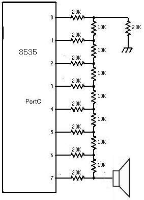
This is a simple D/A converter created with a 20KOhm resistor pack and a 10KOhm resistor pack.