Security Entrance System
EE 476 Final project
Abram Connelly
Matt Harren
Appendices:
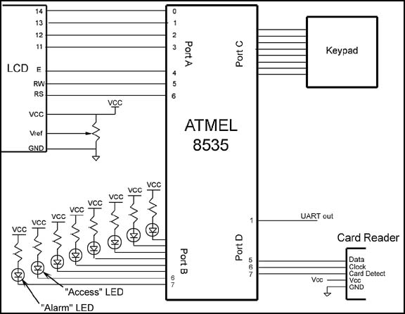
Schematic of the hardware
Our sourcecode.
Our security system is a stand alone device that allows access to registered users identified by their magnetic cards.(For this project, "access" is represented by a lit LED, showing how the system could be used to control an external locking mechanism.)The system includes features such as:
- Multiple accounts, including Administrator accounts (which can create, modify, or delete the other accounts). The account information is stored in non-volatile EEPROM memory, so that it is maintained even if the system is reset.
- A "lock down" of the system when someone tries to gain access by repeatedly swiping incorrect cards.
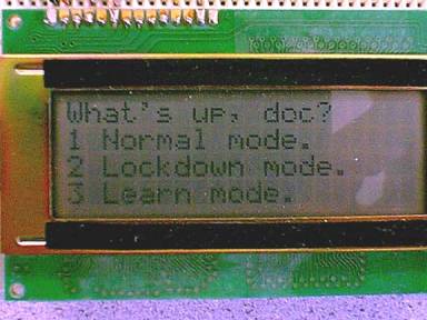
- A 20x4 LCD display to give the user feedback on the current state (such as "Access allowed." or "try swiping the card the other way.") and to prompt administrators for commands. All messages printed to the LCD are simultaneously transmitted to an RS232 port, so that all activity can be logged by a PC.
There are three basic modes of operation:
Normal Mode:
When a card is swiped, the system compares the number on the card to the list of numbers in the EEPROM database compare the number in its database. If a match is found, an the EEPROM lookup reveals that the account has not been disabled, the system prints a friendly message and lights the "access" LED for 4 seconds, representing the time that the door would be unlocked.
If the account number belongs to a system administrator number, then the administrator is prompted to enter a new mode via the keypad.
If more than three invalid attempts are made in a row, (i.e. presumably by a person who is not authorized for entrance) then an LED representing an alarm is activated, and the system goes into a lockdown mode.
Lockdown Mode:
While the system is in Lockdown mode, only administrators will be recognized. In addition to the ability to lock down after several failed attempts, this feature provides a convenient way for administrators to temporarily disable all non-administrator access, without having to modify each account individually,
Learn Mode:
This mode allows administrators to modify the database of magnetic card information. There are 4 levels of permission:
0:Delete account (account is deleted, and the space allocated to the account is freed)
1:Disable account (account is temporarily disabled, but remains in the database)
2:Normal permissions. (user may get access, unless the system is in lockdown mode.)
3:Administrator level permissions.
The administrator who puts the system in lockdown mode is prompted to swipe the card that will be modified, and can then choose any of the four permissions levels to assign to that card. If the card already exists in the database, it is overwritten with the new permissions level.
 Hardware:
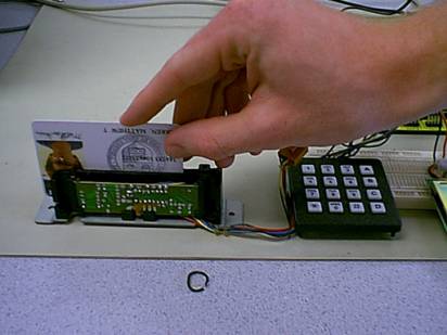
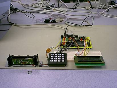
This system consists of an Atmel 8535 MCU and three other main components. The first is a magnetic card reader, which is used for authentication. The second is an LCD display, which will be used for messages to users. The third is a keypad which is used for by system administrators to configure and maintain the system.(See attached schematic.)In addition to these components, a UART connection allows real-time logging to the PC.
Card Reading:
The card reader has a 5-wire interface:
Red: +5v
- Black: ground
Orange: Data
Brown: Clock
Green: Card Detect
Data and Card Detect are active low (data held low represents a logic '1') and data is read on the falling edge of the clock.
On typical magnetic cards, there are three tracks where information is stored. Most card readers (including this one) only read track 2. Furthermore, track 2 is where most useful information is stored, such as credit card numbers for credit cards, or Cornell ID numbers for Cornell cards.
Track 2 has a potential to store 40 characters, each character consisting of 5 bits, 4 for data, and 1 for odd parity. The least significant bit is transmitted first, with the parity bit transmitted last. Zero through nine represent decimal digits, the other 6 characters are for control. A start sentinel character (0b1011) indicates the start of the data block, and an end sentinel character (0b1111) indicate the end of the data block. If the start sentinel and end sentinel are not present in the data read, this indicates a bad read.
Because of limited EEPROM space, our system only looks at characters 9 through 14.These were chosen to correspond to the 6-digit ID number on CU IDs, but almost any credit card or ID card with a magnetic stripe can be used in the system, since these digits typically correspond to some relatively unique substring of the card number.
Our program was implemented as a state machine with 11 states. 7 of these states control the card reading, while the others perform lookups and writes to the database.
The database is stored in EEPROM, which gives it 512 bytes of space in the 8535.Each entry requires 8 bytes (6 characters of ID plus permission information), allowing a maximum of 64 users in the database.To add a new user, the system searches through the database to find the first open slot, or prints a message to the display if the database is full. Timer 0 is used for a 1 ms time base, which allowed us to add appropriate delays to our LCD and UART transmissions, and the Timer 1 ISR clears the display and turned off the access LED 4 seconds after each message is printed.
The system works reliably, and has no known bugs. Cards are almost always successfully read on the first try as long as they are held reasonably straight while swiping (swiping cards at an angle prevents the reader from reading the entire card number.)
If we were to add to the project, we would experiment with adding a card writer (our card reader can’t be used to write cards).Also, we would replace the access LED with an actual mechanical latching mechanism.
For more information, write to mth13@cornell.edu or amc45@cornell.edu.