
Introduction High Level Design Program/hardware Design Results What Would We Do Different
Appendix Pictures Schematics Example Web Output
Imagine being able to monitor the status of a given room or area from anywhere in the world, at anytime. In today’s booming technological atmosphere, this dream doesn’t sound so far off. However, imagine being able to do this cheaply, while not sacrificing efficiency and functionality. Our microcontroller web-monitored thermostat does exactly this. It offers flexibility and functionality at a very low cost.
While conceiving our final project idea, we thought of many applications where a thermostat could be remotely monitored using a serially connected web-server. Food businesses or warehouses would be able to continually monitor temperature histories as well as possible problematic conditions that could potentially destroy their inventory. Dense computer labs utilizing millions of dollars of high-end computer equipment need to be carefully temperature controlled. Wouldn’t it be helpful if the lab administrator could monitor the lab’s environment as well as its individual computer conditions?
Our web-monitored thermostat continually monitors a room temperature, and using the power of Matlab, sends this information to a web server for posting on the Internet. Simultaneously, the device compares the current temperature to some temperature threshold, which the user sets, to determine if a fan should be turned on. The device’s feature set is completely flexible and very easily changed through software and minor hardware changes as per customer need basis.
Our thermostat uses the Atmel AT90s8535 microcontroller to control and interface the devices involved. Our main objective was to accurately measure room temperature. We achieved this using National Semiconductor's LM35 temperature sensor chip, which outputs some voltage based on the temperature in Celsius. The microcontroller analyzes this voltage using its Analog to Digital Converter, and displays this temperature on the LCD. Simultaneously, the current temperature and fan status is outputted via the Universal Asynchronous Receiver and Transmitter (UART) to be interfaced with Matlab and sent to a web server for output on the Internet. At any time in this process, the threshold temperature can be changed by the press of a pushbutton. This will make Matlab prompt the user for a new threshold, and the input is sent back to the microcontroller via the UART.
We designed our device to work at a range of 0 degrees Celsius to 150 degrees Celsius. The specification for the LM35 chip says that for every degree Celsius the chip measures, the output voltage will be 10mV, and that the device is accurate to +/- .5 degrees. We used a reference voltage of 2.55 Volts on the Analog to Digital Converter to ensure an 8-bit temperature for simplicity, and to ease the mathematical calculations necessary to convert the digital input to a hexadecimal temperature. The math required came down to a simple shift. We simply shifted the digital 10-bit input by 2 to the right, resulting in a division by 4. For example, if our input is 512, we would divide by 4 and get a temperature of 128 degrees.
The microcontroller polls for a new temperature about once every second, and then outputs it to Matlab and the LCD. Matlab will then analyze the input from the UART and format HTML for viewing on the web. Every 5 readings, a history graph is updated on the web. This history graph contains up to 20 data points, with each data point containing the precise time that the data was recorded, and the temperature reading. The web page also shows the status of the cooling fan through text and an animated graphic.
The threshold temperature defaults to 25 degrees Celsius. If the user wants to change this, a pushbutton must be held down. Matlab will prompt the user for the threshold temperature, and the updated threshold will be displayed on the LCD along with the current temperature.
Our assembly code revolves around a simple loop. Before the loop, the program sets up a handshake with the web-server to ensure synchronization. Then the program enters the main loop, which acts as a task scheduler. Here is the pseudo-code:
main:
Get temperature
Send temperature to LCD and temperature, fan status and button status to UART
Check for button press
Get new threshold
Set fan status
goto main
Get_temperature reads the digital input from the ADC and shifts the 10 bit input into 8 bits. This hexadecimal temperature is then sent to Ana_to_LCD to get displayed on the LCD and sent to the UART for Matlab interception. Check for button press does exactly that. If the pushbutton to signal a change in threshold is pressed, this routine will record this action and Get_new_threshold will ask Matlab for a new one using a blocking polling UART send/receive routine. Finally, Set_fan_status compares the current temperature with the threshold temperature to determine if the fan should go on or off. If the temperature equals the threshold or above, the fan will turn on. If the temperature is below the threshold, the fan will go off. See appendix - Final.asm for this code and the rest.
We utilized 2 interrupt service routines. Timer 0 overflow was used for miscellaneous timing features, like intermittent delays for the LCD code. Timer 1 compare match A was used to turn the ADC Start Conversion bit on once per second, ensuring that at the very next time the loop got to Get_temperature after the interrupt, it would know to start the conversion and get the new current temperature. We had to continuously convert hexadecimal temperature to ASCII digits for output to the LCD and to Matlab. This was done by subtracting 100 continuously to find the hundreds digit, subtracting 10 continuously to find the tens bit, and the slack would be the ones bit.
Matlab itself does not include an API for interfacing with a serial port. We instead used a toolbox called CPort, found on the MathWorks website and written by Eyal Doron. Cport included all the necessary routines for opening ports, setting up ports (9600 baud, 8 bits, 1 stop bit, no parity, etc.), sending characters, and receiving characters. We used a simple GUI to have the user enter the threshold temperature. The Matlab code constantly looks at the input stream from the UART and decides if there is some error in the bitstream. If an error is detected or a CTRL-C is detected, the program will exit. Here is an example bitstream:
t 0 2 5 0 0
The t is used as a synchronization character. The next three characters are the current temperature. The fifth character is a fan status bit 1 for on, 0 for off. The sixth bit is a button status bit. Was the button recently pressed? 0 for off, 1 for on.
Every 5 data points, the Matlab code will update the time vs. temperature plot, output it to a JPEG image file, and update the web page’s graphic file. Each time the current temperature is updated, the code updates the HTML with the new statistics. We picked every 5 times because the Matlab conversion from a figure to a JPEG graphic file is very processor intensive, and we found that it served as a bottleneck for the whole device operation.
When the button is pressed, Matlab asks for a threshold, and sends it to the microcontroller. The format is simply the three characters of the threshold temperature in the normal ASCII format. The microcontroller processes this input and then for handshaking purposes outputs a 'g' to the UART to tell the web server that all is ready to be started once again.
To trigger the fan on from a port pin, we used a simple power transistor (TIP31C) configuration, where the motor was connected to a 12 volt source and the collector of the BJT. The port pin first went through a 1k ohm resistor, which was then fed into the base of the BJT. The emitter was tied to ground. We also included a diode across the motor to protect the port pin from damage.
Although we suffered the usual pitfalls along the way, in the end everything turned out well. We accomplished all of our goals of integrating the computer serial interface with the microcontroller, and merging the microcontroller hardware with some analog circuitry and a computer hardware/software interface. We found the temperature was usually near 1 degree accuracy, which is not too far from the LM35 specifications. The web interface was a bit slow in the beginning, mostly because we were updating the time vs. temperature plot to a JPEG every time there was new input. Setting this to every 5 points helped much, and this setting can be tweaked even further for better performance. The CPort interface was a bit difficult to get working in the beginning since every time we went to read from the serial port, Matlab would crash and bring Windows down with it! As we discovered later, this was due to a timeout setting. This timeout setting controls how long the interface looks for a character from the UART, and by default the timeout is forever. Setting this value to something reasonable like 10ms worked well. Also, CPort was attempting to do DTR flow control and handshaking by default, and turning that off in CPortconfig was a necessity.
What We Would Do Different Next Time
We spent many hours trying to get a keypad working on Port B, so that the user could also enter the threshold temperature locally. We had very sporadic problems, apparently because of slight differences with Port B than the other Ports. For instance, only the first row of the keypad would respond to press. If we had to do this again, we would take the 8535 chip off the developer board and connect the keypad directly to the chip with minimal hardware in between. We couldn’t use Port A since we were using the Analog input port for the temperature probe, and we needed all 8 pins for the keypad. We couldn’t use Port D since the UART uses pins D0 and D1 for receive and transmit. Finally, Port C was being used by the LCD screen, so we were out of ports. Maybe a better thing to do next time would be to use a chip with more ports.
Instead of using Matlab, we would use a C interface with Linux. This way we would easily be able to run CGI scripts and the web server. Also, the C interface would have been less clunky then Matlab’s entire program interface, since we wouldn’t have to have Matlab open.
If we had more time, we would have liked to have the user be able to enter a new threshold from the web page. This would require some sort of CGI script and ftp interface, and we have never used either so we would have had to learn it in detail.
Assembly Code:
Final.asm - This is the assembly code.
AT90s8535 Include File - Standard include file for Atmel AT90s8535
Matlab Code:
TempInput.m - The main matlab interface.
Get_threshold.m - The matlab GUI interface for input
Get_value.m - Processes input from the GUI
UpdateHTML.m - Updates the html file output
UpdateTempGraph.m - Updates the time vs. temperature graph
An example of the web page output:
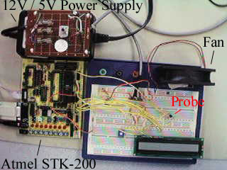
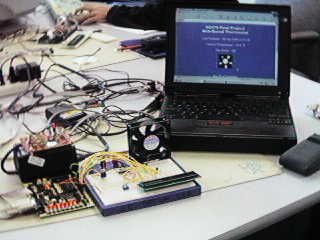
Figure 1: A Picture from above of the setup
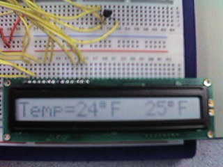
Figure 2: The display of the current temperature (left) and the threshold temperature (right)
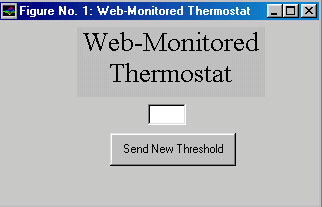
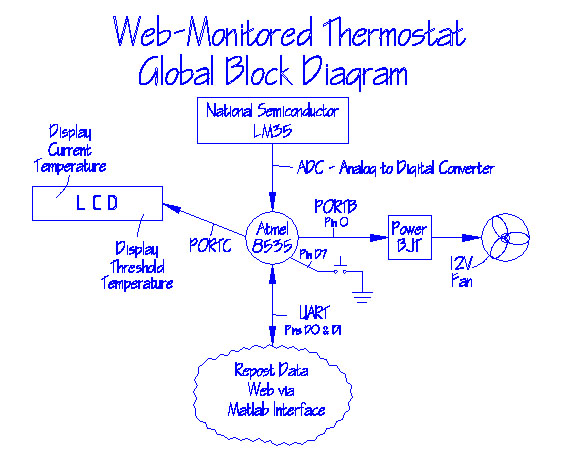
Figure 4: Global Block Representation

Figure 5: Power Transistor Based Electronic Relay