
P O N G
Eric Milkie
Jomar Ochoco
Introduction
For our EE 476 final project, we wanted to make something that would be fun and also allow us to use many of the different embedded control techniques we have learned throughout the semester. We thought a game would be a perfect example. After considering some other games, we chose Pong. We felt that there would be enough graphics to make an interesting looking game, but still does not require complicated graphics algorithms, which would be difficult to implement on an LCD and relatively slow processor.
Read about the real
PONG
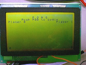
Opening screen display
High Level Design
We used an Atmel AT90S8535 microcontroller for this project. We
used the ADC on the chip to read the positions of the potentiometer controllers
(see Hardware). The game is for two player simultaneous play, although we found
it is also challenging and fun to play against yourself using both controllers.
The program is made up of a main game loop which calls a series of
subroutines, and accessory routines that are used before the game starts and
after the game ends. This is illustrated in the diagram below.
Hardware/Software Design
Our main piece of hardware was a 240x128 pixel LCD (ITM240128A). It comes with the T6963 LCD controller, which made using the LCD easy to do. This particular LCD was available for us to use for free and the previous project that used this LCD had had success with it so we felt comfortable using it. The convenience with the controller is that all we had to do was give it LCD memory locations to write to and make sure the LCD status is OK before every operation. Our program manipulates four control bits connected through Port B and eight data bits through Port C.
The LCD's graphical memory, which is directly mapped to the screen itself, is divided into 30x128 sections, each one pixel tall and 8 pixels long. To make a 4 pixel line, you first move to the desired location and then set the desired bits in Port C. After a status check, you can set those pixels using our WRITE macro. These macros were modeled after Reid Gurnee's macros that he wrote to accompany his Digital Oscilloscope project.
The LCD requires -16V for the display itself and 5V for the controller. We used a power supply for the -16V and used the STK200 board to supply the 5V.
One of the challenges of displaying graphics on the LCD is dealing with objects that overlap byte boundaries in LCD memory. We designed the paddles to be not on a horizontal byte boundary, but this was unavoidable with the ball. The draw-ball routine switches on the 7 cases of ball position with respect to the byte boundary. Each of the 7 cases has a different bitmap (or two) depending on the ball's position within the byte. Erasing the ball just blanks the entire byte or two-bytes that the ball occupies.
Another important part of the software was updating the ball location and checking if the ball has hit a wall or a paddle. To update the ball position, the x and y velocities were added to the x and y coordinates of the ball. When the ball is traveling towards 0 in the x or y plane, the velocity is negative (0xFFFFFFFF if speed=1). After updating the x and y locations of the ball, the program checks if those locations are outside locations 8-232 in the x direction or 0-124 in the y direction. If the location is outside in the y direction, a wall has been hit and the wall sound is played. The ball speed in the y direction is reversed (negated). If the location is outside in the x direction, the program checks if the y location is within the range of the paddle. If so, a different sound is played and the score is adjusted appropriately. The game ends when one of the scores reaches 4, after which an end-game message is displayed and a tune is played. The game then starts anew after a button press.
To start the game, a player must press Button D0. Variables are randomized in the background while the program is polling for the buttonpress. We were careful to start the ball in the middle and only randomize the ball in the y direction or else the ball may fly off the screen before a player has a chance to hit it. Another addition we made was to speed up the ball in the x direction with every fourth paddle hit. This made the game much more interesting.
 |
For our paddle controllers, we decided to use large
potentiometers. Another option we considered was having the two
users push buttons to move the ball, but we thought the game would be much
more accurate if we could match positions of the paddle on the screen to
certain resistance values. This is similiar to other video games that
use a mouse or trackball to control a player on the screen. Fortunately,
we already had a resistance measuring routine from our previous
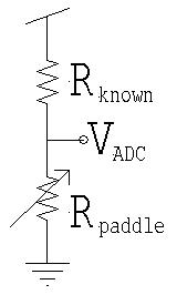
voltmeter/ohmmeter project. One can see from our schematic that the
8535 ADC input is connected to a voltage divider. Aref is set to
4.096V so that it measures exactly 4mV. We wanted to use this kind
of voltage divider to prevent the ADC read from going above 4.096V.
From the measured voltage, we find the resistance using the following
equation: |
At first, our paddle was 8 pixels long giving us 120 possible positions for the paddle for a 240x128 pixel screen. The maximum resistance is approximately 15.6kOhms. Therefore, to find the position on the screen, we just have to divide the resistance by 130. Our multiply and divide routines were copied from the Atmel web site and modified slightly to serve our specific purposes. Later in the project development, we decided to make to double the length of the paddle to make the game easier for the players and all that was needed was to adjust Aref so that the paddles can reach both ends of the playing field and no further. We knew that there are other ways of finding the position without so many multiplies and divides, but we quickly realized that time was not an issue since our test ball already moved much too quickly for the human eye to see. The game now employs a small delay routine (using timer 0) to keep the game challenging but not impossible to play.
To make the sounds for our game, we programmed the timer1 compare/match to toggle Port D7. To have it play different sounds we set OCR1A to play a certain frequency and the Z register is a counter for the duration of the sound. The timer1 ISR also decrements the Z register and turns itself off automatically once the Z register has decremented to zero. This allowed us to have sound playing "in the background" while the game continued to play. Otherwise, there would have been annoying pauses during the game whenever sounds were played.
We found that Port D had only enough current to drive an earphone and not enough for a larger speaker. To get around this, we connected Port D7 to an LM 358 op-amp in a voltage follower configuration. This way, the necessary current is from the board and not directly from a port pin.
Results
The game works great and we added enough challenges to make the game interesting. Our expectations were met for this project. To see for yourself, you'd have to play the game of course.
What we would do next time
There are several improvements that can be made given more time. One improvement that we could have made is to add a DC-DC controller circuit. The LCD we used required -16V for operation and we had to use a second voltage source to provide this bias. With a suitable DC-DC controller we could have converted the voltage from a 9V battery to the -16V we needed. Similarly, we could have had another battery connected to a voltage regulator that could have provided the 5V needed by the microcontroller and the LCD controller. Another improvement would be to add a physical case to secure the controllers/LCD and hide the wires. This would improve the aesthetics of the project and make the game less fragile.
We also had trouble keeping the code size small enough to fit in program memory. To reduce the size more, we could rewrite more of the LCD macros as subroutines, and use more optimized draw and erase subroutines.
Schematic


Program Listings
Source Code pong.asm
LCD macros macros.asm