AT90LS8515 Digital Message Machine
EE476 Final Project
Jon Winslow
Introduction
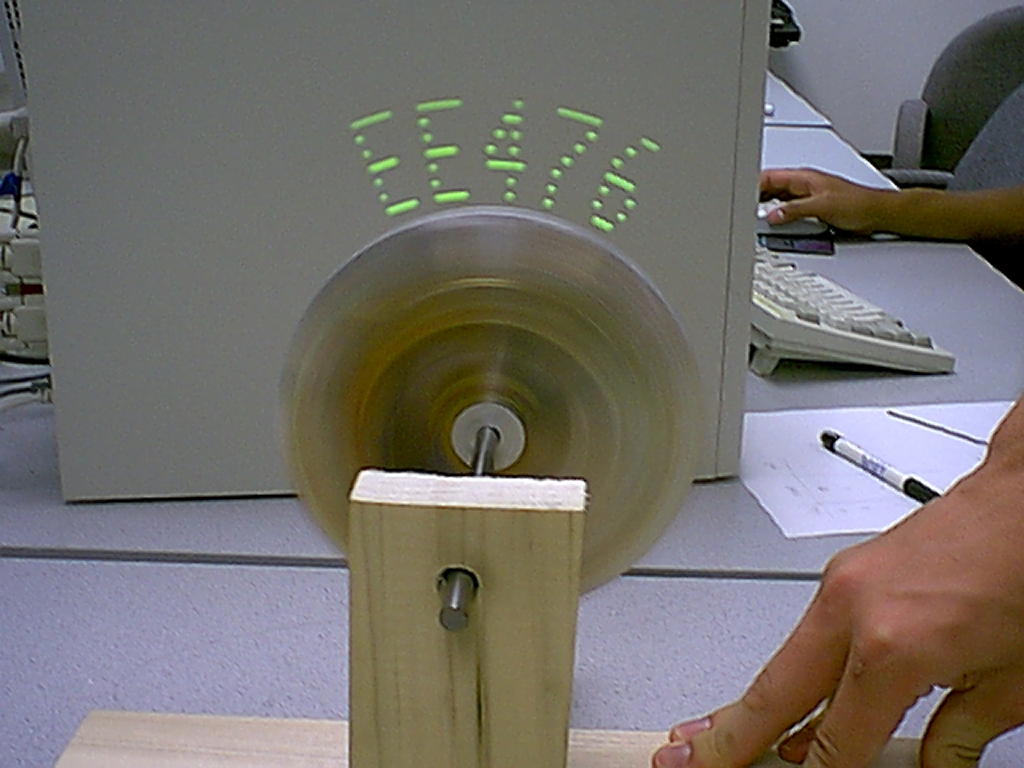
For my final design project I decided to design and build a digital dot matrix message device. I've seen devices similar to this before and I wanted to find out if I could build one myself. The display consists of 7 LEDs in a vertical row. By moving them fast enough back and forth over each other, I can display a message which appears to be generated by a 7*n matrix of LEDs and not a single column of LEDs.
High Level Design
My first thoughts on this project focused on the most important aspect of the project which was to get the LEDs moving fast enough and refreshing often enough for the message to be perceived as a constant display with the LEDs moving. I knew the microcontroller was fast enough, and I hoped that the LEDs could turn on and off fast enough. The major hurdle I faced was how to actuate the LEDs. My first choice was a wand that oscillated back and forth. However, when the idea of creating a spinning disc was offered, I jumped on it. I could create a disc out of aluminum and mount all of my electronics on it. The device would be completely stand-alone (which is cool) and it would be easy to spin it at a fast enough rate to meet the hardware requirements. After that, it was merely a matter of writing my code to turn the lights on and off.
Hardware Design
The hardware portion of this project presented as much of a challenge as the software portion. Once I decided on using a disc to spin the LEDs, I needed to figure out how to manufacture this disc. I decided to go with aluminum, since Upson has a metal shop and my roommate is a Mechanical Engineer who could help me out with the machining. One thing that is vital to the success of this project was the ability to spin the LEDs at a fast and smooth rate. If the disc were to wobble, it would significantly degrade the performance of the display. I choose aluminum as my material since it could be machined easily and in such a way that it was precise enough to rotate smoothly.
After talking to my roommate, the guys in the machine shop and a few others, I came up with some preliminary drawings that turned out to be relatively close to the final product.
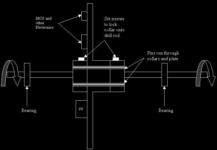
I knew I needed a way to mount the rod and disc when it was finished so I decided to use Roller Blade bearings to mount the rod. I choose and appropriate sized rod and a disc which was 3/4" thick and 6" in diameter and I was off and running. The machining took so much longer than I anticipated. This project never would have made it to fruition without the tireless help of my roommate Greg Gombert who helped me machine the disc, which I could have never done alone. The specs show the basic design for the disc. We drilled a hole down the center for mounting the disc on the rod. We attempted to machine down the disc so the thickness was much less than 3/4" everywhere but the center, but I soon realized that this would take hours, and a couple hours of machine time is close to a day real time.
After we got the hold down the center, we needed a way to attach the disc to the rod. To do this, we made two aluminum collars. We machined collars that could be attached to the rod on either side of the disc, and then made it so that the two collars attached to the disc. After that, I built a wooden stand to hold the bearings that would support the rod and I had a spinning disc on a rod. Doesn't sound like much, but it took long enough to build.
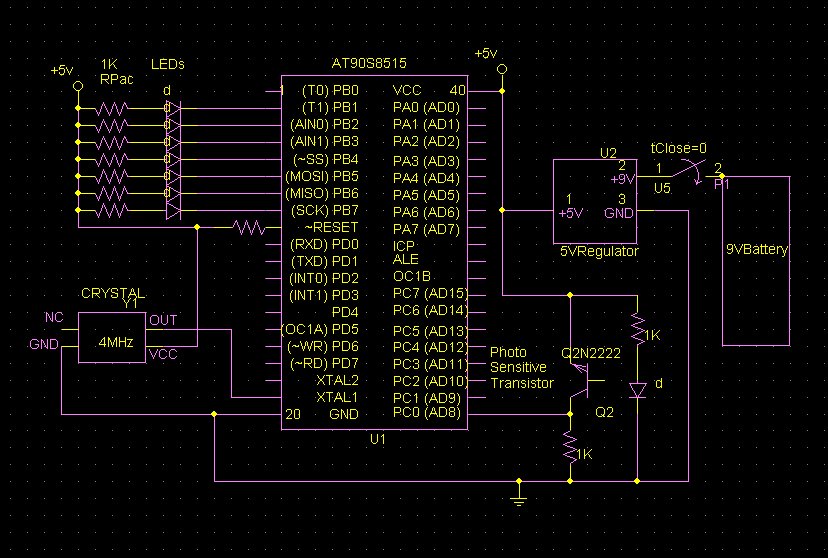
Electronic Hardware Design
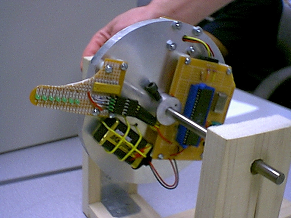
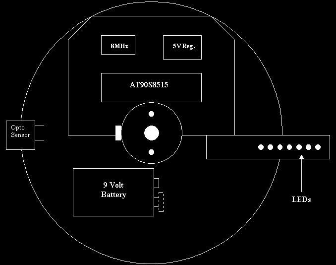
The electronic hardware design for this project was relatively straightforward. The microcontroller is very easy to make stand alone, requiring power, ground and the oscillator. The LEDs were very easy to design, requiring only a 1k RPac with one end connected to Vcc and the other end of the LEDs to PortB. The Sensor used had an LED on one side and a phototransistor on the other. I mounted this on the disc 90 degrees from the LEDs. When the LEDs were at 180 degrees and the LEDs were at 90 degrees, the plane of the photodetector was broken and a signal was read on PortC[0]. This allowed me to measure the period and to use this for the timing for the rest of the design. The only other electronic components were the battery and the regulator. A 9V battery was used for a power supply and a 5V regulator provided the necessary voltage level for the rest of the circuit. A simple switch allowed me to control conductivity between the battery and the regulator.
Software Design
There were two things necessary to getting the project working.
- Getting the right data out of PortB to the LEDs
- Sending that data out at the right time.
The first part required me to make a rather large data table. The table was 8*n where n equaled the number of characters I had in the table. Each letter displayed was a dot matrix 7*5 representation that the LCD data sheet was nice enough to do for me (see appendix A for table.) By looking at this table, I could convert each of the 5 columns of the character into a single byte of data for the 7 LED wand. I also made a table that was 14 bytes long, each byte holding a reference number for the rastorization table. Each character was assigned a value (equivalent to the row number or byte address/8.) It was fairly straightforward to create a state machine that would access these table correctly.
The timing worked out better than I thought it would. I had a double precision variable store the time it took for each revolution and then used that value to calculate all my timing. This means that all the timing is based on the period for the previous cycle and not the current cycle, but since they are so close, it doesn't matter and is entirely sufficient for this application. A double precision variable counting 8uSec ticks allows me to measure periods up to a little over .5sec. Since the disc needs to rotate much faster than this to display a message, this is good range for the period. By shifting this value right by one bit, I have half the period and can easily determine when the LEDs move from 90 degrees to 270 degrees. So I can start displaying the message after half the period has gone by and I can shut them off when the sensor goes off. This easily took care of the first part of the timing requirement.
After I got this first part out of the way and debugged it, I got the disc to display messages. However, as the disc slowed down, the message started moving more and more left (since the number of uSec after the wand hit 270 degrees was a constant.) Also, the length of time between displaying portions of the letter was constant, so the width of the letters continually got smaller. If only I could obtain a value which would allow me to calculate the time after 270 degrees to start displaying and to calculate a value for display spacing so the message would stay in place. Wait, the period! :) I basically used the period and shifted it right or left until I got a value that was appropriate for the spacing between wand displays. I didn't have a specific timing requirement for exactly how long to wait between sending out the rastorization portions of the letters. I could get the data fast enough, it was just a matter of waiting to send it out. So I just played with the factors until I got one that looked good. If the letters were too wide, shift the variable right. If they were too narrow, shift it left.
Next Time
For this project, I can't really think of any major regrets. Therefore, there isn't anything that I really wish I had done differently. However, I do have several things that I could have done to expand on this if I had more time. First thing is it would be very easy to store multiple messages in a table that is 14 characters*n, where n is the number of messages. A simple dipswitch would allow me to change messages without reprogramming the microcontroller. Also, it would be cool to have it display a message for 5 seconds, then change the display to another message. If I wanted to get really fancy, I could incorporate scrolling which wouldn't be immensely hard. There are many ways that I could have taken this even further, and given more time, it would have been cool to do so. All in all, though, I am very satisfied with the way this project turned out.
Appendix