PORTC to DAC (from Lab 5) connected through an op-amp to strengthen the signal before sending it to the speakers. Pins 4,3,and 2 of PORTD used to communicate with MainBoard. Pin0 of PortA used for the 5V rail of the op-amp.
Program/Hardware Design |
Software
MainBoard
Variables:
LCD constants, temporary variables, flags, character arrays (to be displayed on the LCD), array of OCR values, piece definitions, the board
Timer0 Overflow:
Used to debounce the seven pushbuttons: Four states guarantee that one hit of a button corresponds to one rotate or move or other action. The code that executes the appropriate action occurs in state two.
Used to correctly communicate with the SoundBoard: the correct timing for holding the ports high or low for a particular "song"
Used as the seed for the psuedo-random piece selection : an 8-bit variable is incremented every 30msec when the Timer0 overflow interrupt occurs, the lower bits of this variable are used to determine which piece appears. The first piece is chosen when the user hits the "Start" button. Sequential pieces are chosen after the previous piece settles. We found this method worked reasonably well during normal play conditions.
Moving the Pieces:
User interaction with the "Move Left" and "Move Right" buttons corresponds to a shift of the index value. Before shifting we check that it is possible to shift by a logical AND of the current piece with the future location of the game board. Thus we are bitwise ANDing the 16 bits of the game piece with the 16 bits on the game board that correspond to desired position of the piece after the shift. Assuming the shift will be valid, if the user presses "Move Left" the index will decrement by 1, and similarly if the user presses "Move Right" the index will increment by 1. Validity is determined by whether or not the future position is blocked by a game block or the walls of the game board.
User interaction "Rotate Clockwise" button corresponds to a change of piece type, piece[][t]. (Refer to Data Structure of the Current BiLine Piece for an explanation of the piece variable.)
User interaction with the "Fast Down" temporarily changes the value of OCR1A so that the piece temporarily falls faster. Similarly "Drop" changes the value of OCR1A until the pieces falls as far as it can.
Timer1:
Set clear-on-match.
Timer1 was used for the timing of the piece movement down the screen.
The "Fast Down" and "Drop" buttons changed the value of the CompA register to speed up the piece movement.
On each TIM1 COMPA interrupt, we check to see if it is possible for the current piece to drop from current to current - 1 . In the most general sense this operation is the logical AND of the current piece with a 4x4 subsection of game board ranging from index to index +3 in x and current-1 to current+2 in y. (Special cases of this occur at the vertical and horizontal boundaries of the viewable area of the game board, where the conditions are slightly different to compensate for the fact that part of the current piece may be off of the viewable screen.)
If this operation produces a logical 1 in any of the 16 positions, then the piece can drop no further because doing so would cause a collision between the current piece and the game board. In this situation the current piece remains at it current position and becomes part of the game board.
At this point we check to see if current is greater than or equal to 19, meaning that the current piece is above the top of the screen and the player has lost the game.
Assuming that the player has not lost, it next becomes necessary to see if the user has cleared two consecutive lines. We do this by checking to see if in the viewable part of the gameboard two consecutive lines on the board contains all 1's (i.e. all blocks). We note that it is not necessary to check the entire board for these conditions but only combinations of consecutive lines bounded by current -1 to current + 3 . We note that due to our design of the pieces, it is possible to clear only two lines at a time - hence the duality of the name "BiLines". If the player has cleared to lines, we shift each of the lines above the cleared lines down by two.
LCD code:
Basic methods to communicate with the LCD controller in the right sequence.
Multiple methods to run the initialization needed for the LCD and to set up the basic 'look' of the screen.
Method to draw and un-draw the basic box needed for the game pieces.
Method to write integers to the screen (needed to display the level, score, pieces, lines, and hiscore)
Methods for game over, drawing the correctly updated screen, and clearing parts of the screen
Based on our the initialization: The character screen begins at 0x00. To go down one line, we add 40. To go over one character, we add one. We can squeeze 25 lines worth of characters onto the screen. The graphics screen begins at 0x4B0, but we use 0x3C0 as our base address for our boxes - but we only draw half the box for that address. To go down one row in graphics memory, 0xF0 is added. To go over by 8 pixels, 1 is added. The LCD has many options. We chose to turn off the cursor, because when we would update the lines, pieces, score, and level the cursor would appear on the left distracting the player. We changed our cursor direction to down when drawing graphics, and changed it to right when we were writing text or integers to the screen.
The basic sequence for writing a command or data is
1)Put code on PORT A (codes based on data sheet list of codes, see Appendix B)
2)Put cmdSet on PORT C (set A0,WRbar,RDbar,and Rbar high)
3)Put cmdWR or dataWR on PORT C (cmdWr - set A0,RDbar,Rbar & clear WRbar dataWR-set RDbar, Rbar & clear A0,WRbar)
4)Put cmdSet on PORT C (set A0,WRbar,RDbar,and Rbar high)
The LCD/controller data sheets are extremely informative - see Appendix B
SoundBoard
Variables:
Timing constants for the duration of the notes(whole, half, quarter, eighth, sixteenth), state machine variables, temp variables, arrays holding the notes for the various songs, arrays holding the duration for timer1 of the notes corresponding to each note of the song, array of 23 notes (includes sharps, from A to G - almost two octaves), array of 64 samples of a sinewave (sets PORTC which is connected to a DAC for the audio output)
Timer 0 Overflow:
Increments time1, time2 variables which are used in main(void) to call task1 and task2
Timer 1 CompA:
Clear-on-match set
Plays the note by cycling through the 64 samples of the sinewave and changing the output to PORTC accordingly.
Frequency of the interrupt determines which note is played.
Task1:
State machine to handle communication with the MainBoard (3 states, change of song occurs in state 2)
Pins 4,3,2 of PORTD used.
|
001 |
Song 0: game over sound (plays once) |
|
010 |
Song 1: line cleared sound (plays once) |
|
011 |
Song 2: error sound (not used) |
|
100 |
Song 3: Cannon in D (repeats - regular play) |
|
101 |
Song 4: Für Elise (repeats - start up screen) |
|
110 |
Song 5: start/pause sound (plays once) |
|
111 or 000 |
Continue playing same song |
Task2:
Scrolls through the appropriate song array, playing the song once, or continuously depending on the song.
time2 reset based on the song, and appropriate duration for each note played.
HARDWARE
SoundBoard
Sound
PORTC to DAC (from Lab 5) connected through an op-amp to strengthen the signal before sending it to the speakers. Pins 4,3,and 2 of PORTD used to communicate with MainBoard. Pin0 of PortA used for the 5V rail of the op-amp.
MainBoard
PORTD
Used for two-player communication
Used for SoundBoard communication
Pushbuttons
Seven pushbuttons connected to PORTB & PIN7 of PORTC (due to problem pins on PORTB)
Pause, Start - RED Drop, Rotate - YELLOW Right, Left, Fast Down - BLUE
10K resistor pack used for the pushbutton pull-up resistors.
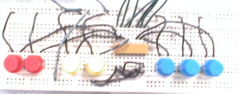
While this buttonpad was fully functional for playing BiLines, we decided to design our own gamepad:
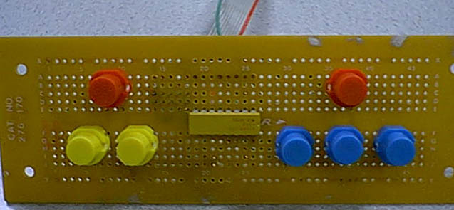
We soldered all of the necessary wiring underneath the board. Aside from the aesthetic advantage, the wires also do not interfere with the hand movements of a hard-core BiLine player. We also ideally positioned each of the buttons to increase comfort and playability for the player.
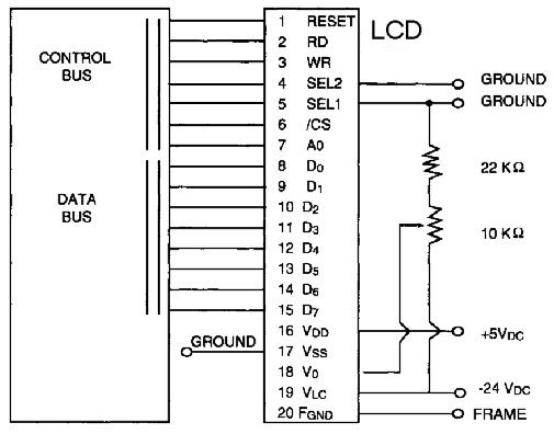
LCD
20 pin header on Seiko G321D 320X200 Monochrome Graphics Display - with the SED1330 Controller Chip from www.eio.com
PORT A - Data Lines
D0-D7 are tristate input/output pins
PORT C - Control Lines
We selected the 6800 family interface by setting SEL1 and SEL2 to ground
A0 is connected to A0
pin 3 (WR) is Enable in the 6800 family (corresponds to RDbar above)
pin 2 (RD) is R/Wbar in the 6800 family (corresponds to WRbar above)
pin 1 is Reset - active low (corresponds to Rbar above)
Fgnd is connected to the frame and should be connected to the system ground