![]()
Introduction
We aim at building
an autonomous vehicle, “Homer”, which can stroll around an environment (e.g.
our lab, or an environment that we build) without getting stuck at obstacles.
That implies that we need a robust algorithm that tells the vehicle how to
steer when it gets into different obstacle situations. The goal
would be to demonstrate a vehicle that will run by itself and not get stuck or
bump into any obstructions.
High Level Description
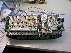
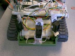
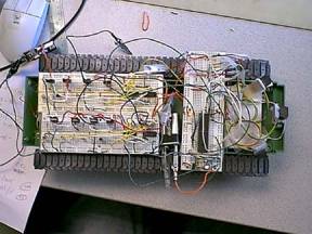
The
following is a high-level description of Homer (our Autonomous tank) :
belts
GP2D02

A “big picture” of Homer
|
|
We used separate speed controllers for the two DC motors which turn the belts separately. Homer turns, or even rotates about an axis, when the motors are run at different speeds. By using the H-bridge speed controller circuit and supplying the circuit with Pulse Width Modulation (PWM) signal as described below, the motors can run at a range of speeds or even backwards. Comparing to the usual car designs which use steering front wheels, this design is preferable because |
1. It allows high flexibility in the vehicle movement. It is not constrained by the maximum turning angles of the front wheels.
2. It allows rotation that is useful in getting away from obstacles.
3. It is
mechanically easy to built (We think the steering front wheels are hard to
build).
|
|
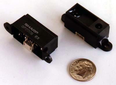
We use three infra-red sensors to measure distances from obstacles. The sensor sends out infra-red pulses and then receives back the reflected signal, and afterwards the distance information is output as serial bits. We need to read in these serial bits into the Atmel microcontroller and convert them to a distance by ourselves in our code. The SHARP GP2D02 measures distances in the range 10cm – 80cm and therefore was suitable for our design. SHARP GP2D02 sensor interface with our Atmel microcontroller will be discussed in detail in the Program/HW design section. |
|
|
We do not have access to the machine shop and hence it is hard to build the physical components of the vehicle by ourselves. Therefore, we purchased a completed toy track vehicle (e.g. tank), and then remove the internal parts and install our own circuitry. |
Program/Hardware Design
|
|
Sharp GP2D02 Infra-red Range Sensors |
Interfacing the
Sharp GP2D02 infra-red range sensors were fairly straight forward.
Following the timing diagram in the specification sheet from Sharp, I
programmed the microcontroller to output a control signal Vin (input signal
into the GP2D02) for the infra-red sensor. Since the Vin pin on the
sensor is initially in the OFF-state and floats high, the microcontroller
outputs the Vin signal to be low to turn on the sensor. The measurement
is initiated by forcing the Vin signal to logic low for at least 70ms or until
the Vout(output signal from the GP2D02) becomes logic high. Once that
occurs, we need to start clocking in the serial bits from the sensor. The
microcontroller must toggle the Vin signal at the rate of 0.1ms. We
toggle the Vin signal a total of 9 times and we clock in the serial bits on the
positive clock edge from Vout. Once the entire byte is read we need to
reset the sensor for another reading. Resetting occurs when we
float Vin high for at least 1.5ms; after resetting we repeat the process over
again for another distance reading.

The serial bits that were read
into the microcontroller were converted into a distance of centimeters.
We calibrated the sensors using a linearization formula. The sensors
output has an inverse relationship to the distance of an object. That is
the further the object, the small the serial bits. Since we don't really
need the sensors to be too accurate, we only need to know the ranges of the
objects from our sensors, we can linearize the curve. We calibrated the
sensors individually for two distances(15cm & 30cm). Therefore any
distances between 15cm and 30cm, we are confidant of its accuracy (In fact we
it seems to be accurate from 10cm to 30cm). Any distance beyond 30cm, we
start to see some deviation from linearized curve. We will consider any
distance beyond 30cm to be infinite.
NOTE: Linearization Formula was
referenced from http://www.barello.net/Papers/GP2D02/multiplexing_gp2d02_sensors.htm
D =
Kg/(X-Ko)
Kg is the gain, or overall
shape of the curve described by Kg/X
Ko is an offset, shifting the curve up or down.
Let D
and X be the distance and output, respectively of your first
measurement.
Let D' and X' be the distance and output, respectively, of the
second measurement.
Kg =
(X'-X) D'D/(D-D')
Ko = (D'X' - DX)/(D' - D)
Since there are three sensors
(Left, Center, Right) we have three Vout signals into the microcontroller.
All three sensors share the same Vin signal from the microcontroller.
Therefore, we take a distance reading for all three sensors at once. It
was necessary for us to use a diode between the microcontroller and the Vin
signal into the sensor. The microcontroller has 5V logic I/O, while
the sensors require 3V logic. According to the specifications, we cannot
directly drive the sensors with 5V. Hence we used a diode, since the
sensor's OFF-state floats high(3V).
|
|
Pulse Width Modulation |
We use Pulse Width
Modulated (PWM) signals to control the speed of the motors. Timer 1 is set to
be in 10-bit PWM mode. To generate PWM signals with different pulse widths, we
simply have to change the values stored in OCR1A and OCR1B. The PWM signals are
then output via the OC1A and OC1B pins.
In our scheme, when we want the
tank to go straight ahead, the outputs from OC1A and OC1B are both steady 5V
(not modulated) so that they go with “full speed”, and when we want it to stop,
the outputs would be 0V. Cases in between going “full speed” and stopping would
results in different PWM signals.
|
|
Central Decision Algorithm |
Every 0.5 seconds
(counted by timer0), the distance information from the sensors are processed in
order to understand the instantaneous environment. The sensor readings,
which are float values on a continuous range, are compared to thresholds so
that the ranges in which they lies are determined:
>= 7 cm && < 20 cm
: range 1 (very close)
>= 20 cm && < 30 cm
: range 2 (close)
>= 30 cm || <=7cm
(infinite, nothing detected)
* Note that the sensors sometimes
give values smaller than 7 cm when the distances are actually “infinity”, and
that’s why we have the “<=7cm” condition.
Based on the 3 “ranges”
determined as above, different control signals are generated. Different
combinations of the three ranges form different “cases”, and in each cases, we
assign predetermined direction bits (Port A0 and A1) values so that the motors
will either turn in the forward or backward direction, and also the right predetermined
PWM signals so that the motors will turn with the right speed. We predetermined
the control signals in each case by experimentation and “common sense”.
In that sense, the control
signals of the vehicle are updated every 0.5 seconds. We want to make sure that
it is up-to-date enough to navigate the vehicle.
|
|
Power Supply |
Since our project
required us to demonstrate our vehicle driving around, we need the
microcontroller off the development board. Having a 9V battery, we used a
power regulator from National semiconductors to supply the microcontroller with
5V. In addition to the power regulator, 2 capacitors(0.2pF and 0.1pF)
were also required to build the power regulator circuit for the
microcontroller.
We also have 6V powering our
motors. The both H-Bridge circuits (LEFT and RIGHT) are supplied with
6V; while the microcontroller with 5V. There is a common
ground.
Also, we used a 4Mhz crystal and
two 22pF capacitors to drive our microcontroller clock.
Results
The results of our project were good. We were able to see that our autonomous
vehicle was reacting correctly to obstacles.
The vehicle's motor was powered by 6V (the original toy was powered by
6V), but didn't really give us strong enough torque. We have tried to build a voltage amplifier to boast the 6V supply
to 9V into the motors. However, 9V
didn't really provide enough torque for the vechile to run smoothly. Finally, we add 2 transistors to make the TIP31 and TIP32
into a darlington configuration. This configuration allowed more current to our motors.
After this modification the tank was work very well.
We discussed possible future
additions to the autonomous tank and came up with one major upgrade. We can make the vehicle capable of accepting
an user destination and move to that destination while avoiding obstacles. We would have to add a keypad, a LCD, and a
electronic compass for such an upgrade.
Overall, we feel that the
project turned out well.

Source Code
Schematics
Microcontoller with
sensors & Motor Controllers
Left Motor Control
Parts
Part
QTY
Sharp GP2D02
3
Toy Tank
1
4Mhz Crystal
1
22pF Capacitors
2
National
Semiconductor Power Regulator
1
0.1pF Capacitor
1
0.2pF Capacitor
1
HD74HC00P (NOR
GATES)
2
74HCT04 (NAN
GATES)
2
1N914 (Diode)
9
TIP32
(Transistor for H-bridge)
4
TIP31
(Transistor for H-bridge)
4
1kOhm Resistor
8
9V battery
1
1.5V battery
4