E ELE 476
Final Project
- EKG Monitoring System -
Jeff S. Lee
Young Ho Cho

Introduction
Unexpected cardiac death, also known as “sudden death” is a
frequently fatal form of arrhythmia which kills more than a quarter of a million
people each year in the United States.
Confronted with the devastating effects of unexpected cardiac death and
with the pursuit of advance understanding of cardiac diseases, my partner and I
– Young Ho Cho and Jeff S. Lee - plan to design and build a heart monitoring
instrument which measures the electrical activity of the heart, also known as
an electrocardiogram (ECG / EKG).
Unexpected cardiac death can be further classified as
ventricular fibrillation - irregular twitching of the ventricles replacing
normal contractions - in which more than half of those victims die within an
hour of the onset of symptoms and before any medical assistance. According to the American Heart
Association's 1999 Heart and Stroke Statistical Update, coronary heart disease
caused 476,124 deaths in the United States in 1996 and since, it has been
identified as the single largest killer of both men and women in this country
and the world.
High
level design
Our EKG
monitoring instrument uses the Atmel Mega103 microcontroller to control and
store the data acquired via EKG monitoring systems involved. Our primary objective is to accurately
measure the electrical activity of heart with EKG monitoring instrument. This is achieved by building an
instrumentation amplifier which is specifically designed for bio-electrical
signal measurement. In addition, two
active filters – one high pass and one low pass – were employed to eliminate
measurement errors. The high pass
filter was used to remove any dc drift with cut-off frequency of 0.2Hz, while
the low pass filter was used to eliminate anti-aliasing effects. More detailed hardware designs are described
below.
User input from
the PinD0 initiates the data acquisition process. Once initiated, the signal
acquired via EKG monitoring instrument goes through the Analog to Digital
Converter of the microcontroller at sampling frequency of 720Hz and this data
is stored in external SRAM. Upon
completion of data acquisition process, the user can initiate transmission of
the stored data via the Hyperterminal to be interfaced with Matlab. Data can be further analyzed with Matlab
software for future studies, such as RR interval analysis, QT interval
analysis.
Hardware
Design
When detecting and recording the EKG signal, there are two
main issues of concern that influence the fidelity of the signal. The first is the signal to noise ratio. That is, the ratio of the energy in the EKG
signal to the energy in the noise signal.
In general, noise is defined as electrical signals that are not part of
the wanted EKG signal. The other is the
distortion of the signal, meaning that the relative contribution of any
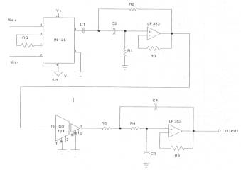
frequency component in the EKG signal should not be altered. To meet the above conditions and
requirements, a design for the amplification system proposed as shown below.
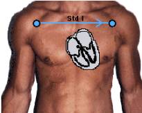
Two bipolar leads shown on the left (i.e., they detect a
change in electric potential between two points) detect an electrical
potential change in the frontal plane. Burr-Brown INA126P
Instrumentation Amplifier - increases the signals by a
factor of up to 10000. Texas Instrument. LF353 Operational Amplifier - High-Pass Filter removes DC base
line drift by cutoff anything below 0.2 Hz. Burr-Brown ISO124 Isolation Amplifier - intended for safety
precaution. This transmits the
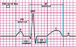
signals optically, thus isolates the circuit from the patient. Texas Instrument. LF353 Operational Amplifier Low-pass Filter accounts for Anti-aliasing effect. The figure displayed on the left illustrates distinctive
sections of EKG signals. All components were powered by one 9V battery thus making
the EKG monitoring system much more safe.
![]()


![]()
![]()
Instrumentation
Amplifier –
The gain of this stage is set by
connecting the external resistor R as shown:
G = 5 + 80 Kohm
/ R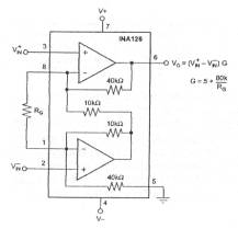
Our case, G = 800
Isolation
Amplifier –
The ISO124 isolation amplifier uses an input and an
output section galvanically isolated by matched 1pF isolating capacitors built
into the plastic package. The input is
duty-cycle modulated and transmitted digitally across the barrier. The output section receives the modulated
signal, converts it back to an analog voltage and removes the ripple component
inherent in the demodulation.

High-Pass Filter
–
The high pass
filter was designed to have a cut-off frequency of f=0.2 Hz
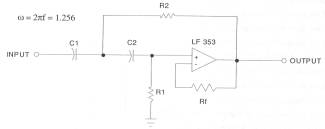
Assuming C1 = C2 = 1uF = C
R1=1.414 /wC =
1.414 /1.256e-6 = 1.125e6 Ohm
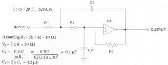
Low Pass Filter
–
The low pass filter was designed for a
cutoff frequency f = 1000Hz.
DC-DC Converter
–
1W Isolated Unregulated DC/DC
Converters from Burr-Brown had been used to supply the power necessary for all
components. One 9V batter supplies
power to Ateml board. Vcc and ground
from Atmel were connected to DC/DC converter in order to produce +12V and –12V
output.
Software
Design
Software – Since
we were using Atmel’s Mega103 microcontroller, we were able to support external
SRAM as well as the A/D converter. The EKG output was inputted into the A/D
converter, where A/D conversion complete-interrupt was used to store the data
into our array. The program starts
taking the data when PIND0 is pushed.
Using timer 2 overflow interrupts, we were able to gain data acquisition
of 720 data points per second. The
program constantly takes data until a character is received through the UART
signaling that the computer is ready to receive the data, or the external SRAM
runs out of space. When the computer is
ready to receive the data, we print out the data to the hyperterminal screen
where the text can by captured by the hyperterm. The data is then plotted in MATLAB.
Things we would
do differently next time - One of the things that we found out too late is that
even though printing out the data is easier to code, it will take much time for
us to print out all the data on to the hyperterm. It did not hit me until too late that printing out that much data
will take time. We have tried to work
with the XModem protocol as originally suggested, but I could not figure out
why the CRC check was not functioning correctly. Another thing that we neglected to do while trying to figure out
the XModem protocol was that we did not put in a reset function for the code.
Results of the
design
The EKG monitoring system
performed very well. The graph shows
Matlab display of the acquired EMG signal at 360Hz after the A-D conversion
process. The bicep muscle was flexed
approximately at 1Hz.
Future
Development
-
Due to the size limit of RAM, the acquired signal can only be
stored for approximately 2 minutes. We would
like to attach a storage device, which would enable us to store the data for
more then six hours in the future.
-
Data transfer is currently performed through two-step
process. Once all data is displayed
through hyperterminal, the result is saved as a text file, which later would be
loaded into Matlab. This is a
cumbersome process and we would like to export the data directly by using data
acquisition system, provided in Matlab.
-
Most commercial EKG monitoring system has more then one channel to
acquire EKG signals. We would like to
add multiple channels to the circuit for future use.
-
The current sampling frequency is set to be 720 Hz. However, we
would like improve this by adding a User Interface that would allow adjustable
frequency in the future.
Appendix
EKG Monitoring System
Block Diagram
![]()
Source Code
//Final Project - Young Ho Cho, Jeff S. Lee
//EKG monitor source code
//Takes 720 data points every second from the output of the A/D
converter
//when PIND0 is pushed.
The result is outputted to the hyperterminal
#include <mega103.h>
#include <stdio.h>
//for debugging using printf, etc
//timeout values for each task
#define t1 1
#define t2 30
#define maxData 30000
//timer 1 constants
#define prescale1 1
#define clear_on_match 8
//the subroutines
void sampleData(void); //test
for button press
void keyCheck(void); //for
non-blocking
void initialize(void); //all
the usual mcu stuff
unsigned char reload; //timer
0 reload to set 1 mSec
unsigned char time1, time2; //task
scheduling timeout counters
unsigned char cmdReady; //set
when command is received
unsigned char stop; //stop flag
unsigned char data[maxData]; //array of data
int index; //index
//**********************************************************
//timer 2 overflow ISR
interrupt [TIM2_OVF] void timer2_overflow(void)
{
//reload to force 1 mSec
overflow
TCNT2=reload;
//Decrement the three
times if they are not already zero
if (time1>0) --time1;
if (time2>0) --time2;
}
//**********************************************************
//ADC interrupt overflow ISR
//when A/D converter is done, it reads the output and stores it
interrupt [ADC_INT] void ADC_done(void)
{
int temp;
temp = ADCW;
temp = temp/4;
data[index] = (char)
temp;
index++;
}
//**********************************************************
//Entry point and task scheduler loop
void main(void)
{
initialize();
//main task scheduler
loop -- never exits!
while(1)
{
//sampleData();
if (time1==0) sampleData();
if (time2==0) keyCheck();
}
}
//**********************************************************
//sampleData -- sample
the data if array not full
void sampleData(void)
{
int i; //used for indexing in for loop
time1=t1; //reset
the task timer
if(index==maxData) {}
//if the data array is
not full, or it's not ready to output data,
//read data
else if(cmdReady==0
&& index<maxData)
{
ADCSR = ADCSR | 0x40;
}
//if the comp is ready to
output data, print the data
if(cmdReady==1 &&
stop==0)
{
for(i=0; i<index;
i++)
{
printf("%d",data[i]);
}
cmdReady=2;
stop=1;
index=0;
}
}
//**********************************************************
//keyCheck -- non-blocking
keyboard check every 30 mSec
void keyCheck(void)
{
time2=t2;
if (USR.7) //RX
done bit
{
cmdReady=1;
}
if (!PIND.0) //PinD0 pushed
{
cmdReady=0;
}
}
//**********************************************************
//Set it all up
void initialize(void)
{
// Port A
DDRA=0x00;
PORTA=0x00;
// Port B
DDRB=0xff;
PORTB=0x44;
// Port D
DDRD=0x00;
PORTD=0x00;
// Port E
DDRE=0x00;
PORTE=0x00;
//serial setup for
debugging using printf, etc.
UCR = 0x10 + 0x08;
UBRR = 25;
//external SRAM
MCUCR = 0x80;
//set up timer 2
//for 720 data points per
second
//86.8 x (64x.25) microSec
= 1.39 mSec, so prescale 64, and count 87 times.
reload=256-87; //value
for 1 Msec
TCNT2=reload; //preload timer 1 so that is interrupts
after 1 mSec.
TCCR2=3; //prescalar to 64
TIMSK=0x40; //turn on timer 0 overflow ISR
//init the task timers
time1=t1;
time2=t2;
cmdReady=2;
stop=0;
index=0;
ADMUX.2 = 0;
ADMUX.1 = 0;
ADMUX.0 = 0;
ADCSR=0x80 + 0x09;
//crank up the ISRs
#asm
sei
#endasm
}