Introduction
Sound byte
For our final project, we are redesigning the classic battleship game to suit the needs of engineers. We are removing the need for communication, but keeping the feel of battleship.So what are we really doing?
Instead of having engineers mumble battleship attacks, all communication is handled by two micro controllers, one for each player. The players interact with their micro controllers through the game board, a keypad, and a LCD. The micro controllers then talk to each other to play the game.Why?
We wanted a project that we would actually use and that involved building components. Given our interest in games, we thought building a game with an interactive board would be both challenging and cool.What is Battleship?
High Level Design
Battleship is a game that involves both strategy and luck. The goal is to conceal the location of your ships while finding and destroying your opponent’s ships. Each player has a board to strategically place their ships which are located by multiple grid coordinates. A player ‘hits’ his enemy’s ships by correctly guessing the coordinates. Each player also has a board to record previous hits or misses. You win by destroying all your enemy’s ships.
The user-interface consists of two identical setups, one for each player. Each setup consists of a LCD display, keypad, and a battleship board. The LCD display is used to prompt the user for commands and to display the results. The keypad is used to enter in the attack coordinates. The battleship board is for the user to place their boats. All the components of the setup are tied together and controlled by an ATMEL 8525 microcontroller. The two setups then interface with each other through the serial communications port on the Atmel STK-200 development board.
Program/Hardware Design:Hardware:
Port Connections:
One of the big issues we had in designing and building our setup was the limited number of I/O ports. For each setup, we had four input devices which were:
- LCD display
- Keypad
- Game board
- The other game setup
The LCD display and keypad each took up an entire 8-bit input port. Since the Atmel 8515 MCU only has four 8-bit I/O ports, this leaves us with two ports for the game board and the connection to the other setup. However, due to the way we wanted to create our scanning routine for the game board, a single 8-bit I/O port would only allow us to create at most a 4x4 gameboard. In order to create a larger gameboard we would need another I/O port. To add more to our troubles, some of the pins of some I/O ports had other functions which lmited the ports functionality, namely PORTD and PORTB. Well, without further a due, here's what we decided upon:
- We placed the LCD display on PORTA since there were no known limitations on any of PORTA's pins. Also, we did not fully understand the function of all of the input pins of the LCD and so it would be best to give the LCD what it wants.
- In order to communicate with the other board it is not necessary to dedicate an entier 8-bit I/O port. Instead only 1 or 2 bits are necssary and that is exactly what we used. Communications between the two setups was done through the UART on both chips which uses only pins 1 and 2 on PORTD.
- We placed the game board on PORTC and PORTD. We could use all 8 pins on PORTC and 6 of the pins on PORTD. With 14 I/O pins available to us we were now able to create a 7x7 gameboard which is a big improvement over a dinky 4x4 gameboard.
- This leaves the keypad with PORTB. However, in order to read the keypad we needed to toggle the pins between input and output. Two of PORTB's pins were trouble and therefore, we decided not to use them. With only 6 healthy I/O pins we had to reduce the size of our keypad to 3x3, which we were able to work around.
Building the board:
The gameboard is similar to the keypad. We crossed horizontal and vertical strips of conductive foam on a breadboard to create a grid of coordinates. The individual strips were spaced from each other, and insulating foam separated the horizontal and vertical layers. A boat was placed on the grid by piercing a wire where the strips crossed, connecting the horizontal and vertical layers together. We added external pull ups of 1.5M(ohms) because the resistance of the conductive foam crossed together was too large to pull down to GND. Each of the wires was conncted to a port pin to interact with the mcu.
This setup was a 4x4 prototype board. Our original setup had the 7x7 strips in a diskette box to imitate the battleship game board. The individual strips were instead separated by insulating foam, and we melted wire through the box to connect the strips to the port. However, this became an unstable setup for many reasons. It was hard to see if we were piercing where the foam crossed, and the foam would only pull down to around 2V.
Software:
Scanning the board:
Building a board to detect individual locations took awhile because of the physics of the foam. After achieving that, we developed a scheme that could detect horizontal and vertical boats, which was as challenging. However, our scheme could not handle horizontal boats overlapping vertically, that is, sharing a position in the same column.
Since we wanted boats of more than length one, we modified the keypad scan routine so that it could detect multiple locations pressed. Instead of swapping the horizontal and vertical wires as output and input, we pulled up all the vertical wires to VCC and iteratively drove one horizontal wire to GND. To check for multiple locations, for each row we sequentially checked each column for a connection. Basically, we’re scanning through each connection of the grid.
This worked for horizontal boats, but for vertical baots, the state of the other horizontal wires affected the current horizontal wire being checked. We wanted them to be floating nodes. We switched them to inputs, but also had to turn on the pull ups so that they would not be floating at zero. Before checking a row, we had to turn off the pull ups on these other horizontal wires because there wasn’t enough current to draw the wire to GND if there were two sources of VCC.
Our problem case was when the boats formed an “L” shape. This would be instead detected as a square, or four connections. This was because two rows and two columns could be shorted together with three connections, thus shorting the fourth corner. This problem could not be avoided because even though battleship boats are straight, we wanted to be able to detect boats even if other boats were already placed. This changed our specification in that only a single boat can be on the board at a time.
The scanning of the board occurs in the beggining of the game. Both players are prompted to insert their boats one by one. When a player finishes inputting all their boats the board indiciates that it is ready by sending a message to the other board and then waits for the other player to finish. When both players are finished, both boards a different start message depending on who is to begin play.
Coordinate encoding:
A coordinate specifies a single location on the gameboard grid. Each coordinate contains both a row (x) and column (y) location.
We wanted to create an encoding scheme for the coordinates which was space efficient and easy to decode. The following are several reasons why we wanted to make the coordinates space efficient:
- We need to send coordinates between the two setups and we would prefer sending smaller packets of data over the serial connection.
- We have to store the positions of all the boats on the board. This entails storing many coordinates and therefore we want to make each coordinate as small as possible.
- We have to search for and constantly compare coordinates. In order to make this efficient, coordinates should be as small as possible.
We created a structure
coordinatewhich was used to store a single location on the board. Instead of specifying two char variables to store the x and y values we use only a single char to store both values. This is possible because the values for x and y can be at most 7 (max size of board is 7) and therefore each value could be specified using only 4 bits. We chose to store the x value in the upper four bits and the y value in the lower four bits. Therefore in order to decode each coordinate value we need to right shift the char to get the x value and mask the char to get the y value.Storing boat positions:
We used c structures to store each of the boats and all of its coordinates. As stated above we created a
struct coordinateto store a single position on the board. We also created anotherstruct boatwhich holds an array of struct coordinates. We also stored information about the length of the boat and the number of remaining un-bombed coordinates. We allocate memory to store all the boats in the beginning of the program. The memory is allocated as an array ofstruct boat.The boat positions are retrieved through our boardScan routine.
Whenever an attack coordinate is sent, the software has to determine whether or not the attack was a hit. This is done by seraching through all the stored boats. Our search simply iterates over every coordinate stored until a match is found. Coordinate comparison is done by comparing the char value stored in the coordinate strucutre with the received attack coordinate.
Communications:
The two setups are connected through the serial connection on the Atmel STK-200 developement board. The recieving routine used is the same as the one introduced in Lab 4. Communications consists of sending coordinates between the two boards and the results of an attack. Both the coordinates and the result fit into a single char value and therefore could be sent over using the standard putchar method.
Logistics of the game:
The logisitics of the game is all handled in the software state machine. The state machine is clearly explained in the code. We have two main parts of the state machine an attacking part and a defending part.
- The attacking part prompts the player for an attack coordinate, creates the 8-bit coordinate representation and sends it over to the other board which should be in the defending portion of the state machine. The attacking part then waits for the other board to send the results and then displays the results(hit, miss etc.) to the player. The state machine then goes into the defending part.
- The defending part waits for the attacking board to send a coordinate. It then takes the coordinate and searches its stored boat map for the coordinate. If it is found it marks a hit and returns "hit" to the attacker. If the coordinate is not found, a miss is returned. The defending part then switches to the attacking part.
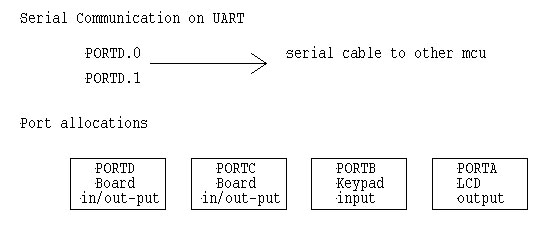
Figure 1. Schematic for Atmel STK-200 ports

Figure 2. schematic for game board
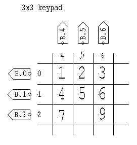
Figure 3. schematic for keypad
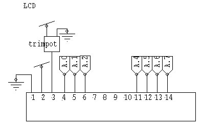
Figure 4. schematic for LCDWe are demonstrating our game by playing a small game of two boats, length 3 and length 2. Since our prototype board was not always stable, we are using the keypad to demonstrate that our board scanning routine works. Only one boat may be on the board when storing the boats into the map. Along with the keypad as a game board, we are using a keypad to enter in the coordinates and an LCD to display messages.
We'll also demonstrate our prototype board, which works but is not as reliable as the keypad.
Conclusion/What we would do differently next time:
We were happy with the software side of the game. Communication between the two mcus worked very well, and we had a good attack/defense state machine. Maybe we would like nicer LCDs to display better (and longer) messages.
Our big problem was obviously the game board implementation. With our current scheme, it would be impossible to avoid the "L" overlap problem. It would be nice to be able to leave the more than one boat in when scanning the board but perhaps this problem is why electronic battle ship never did include a programmed board.
However, to make a more stable board, we would make thicker strips so there would be an easier path to ground and find a better way to short the two strips together. Since our prototype board was built after realizing our first idea with the diskette case would not work, we would have liked to spend more time building this and stronger connections.
Also, since we spent a lot of our time trying to get the board to work, we would have liked more time to work on the aesthetics of the game, i.e. making boats, a cleaner setup, and finishing up the game board. We wanted to cover the game board with a sheet punched with holes indicating where to put in your boats.
Source Code:Main Program: battleshipf.c
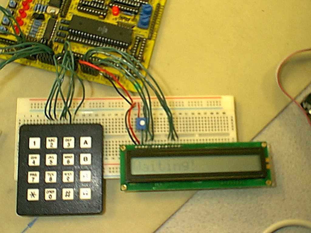
Figure 5. Game Setup
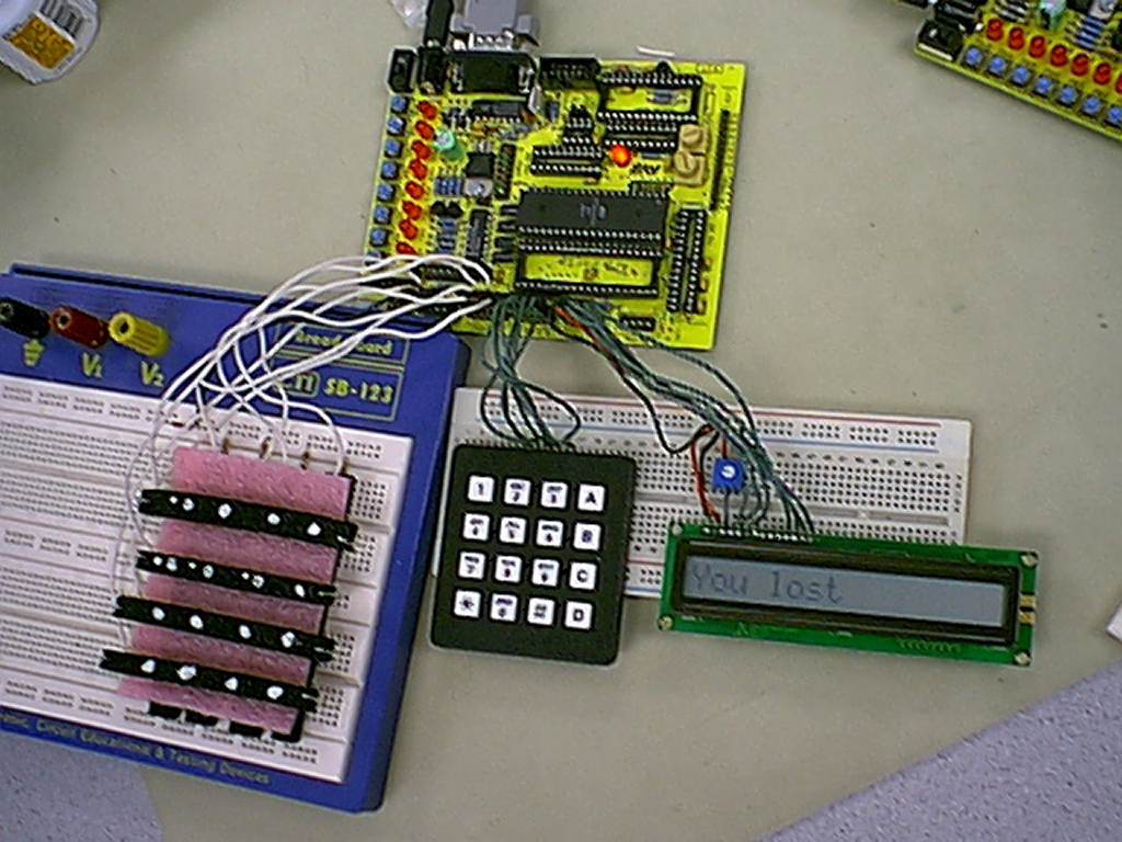
Figure 6. Game setup with gameboard on left.