|
|
|
Pictures
|
|
|
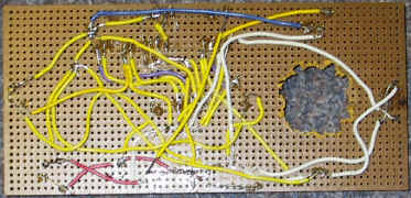
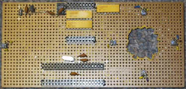
Above are pictures of our final soldered board.
|
|
|
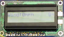
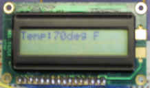
These are examples of what the display might show. On the wind, the B and right arrow indicate that the wind is blowing diagonally from the back and to the right of the direction the golfer is to hit.
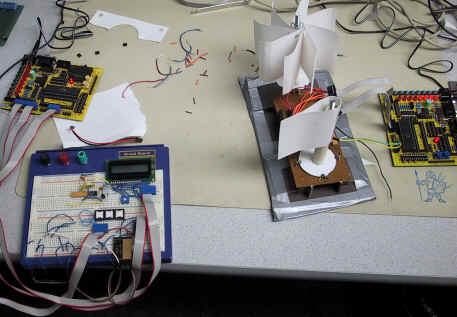
This is our full experimental setup. The components on the breadboard to the left of the LCD and pushbuttons are part of a test circuit for the receiver/transmitter chips. The actual receiver unit is merely the LCD, receiver chip, ATMEL chip and a single pushbutton.
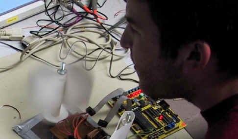
Pete shows us how to generate wind in the lab.