Hardware


The hardware used to create the device are as follows:

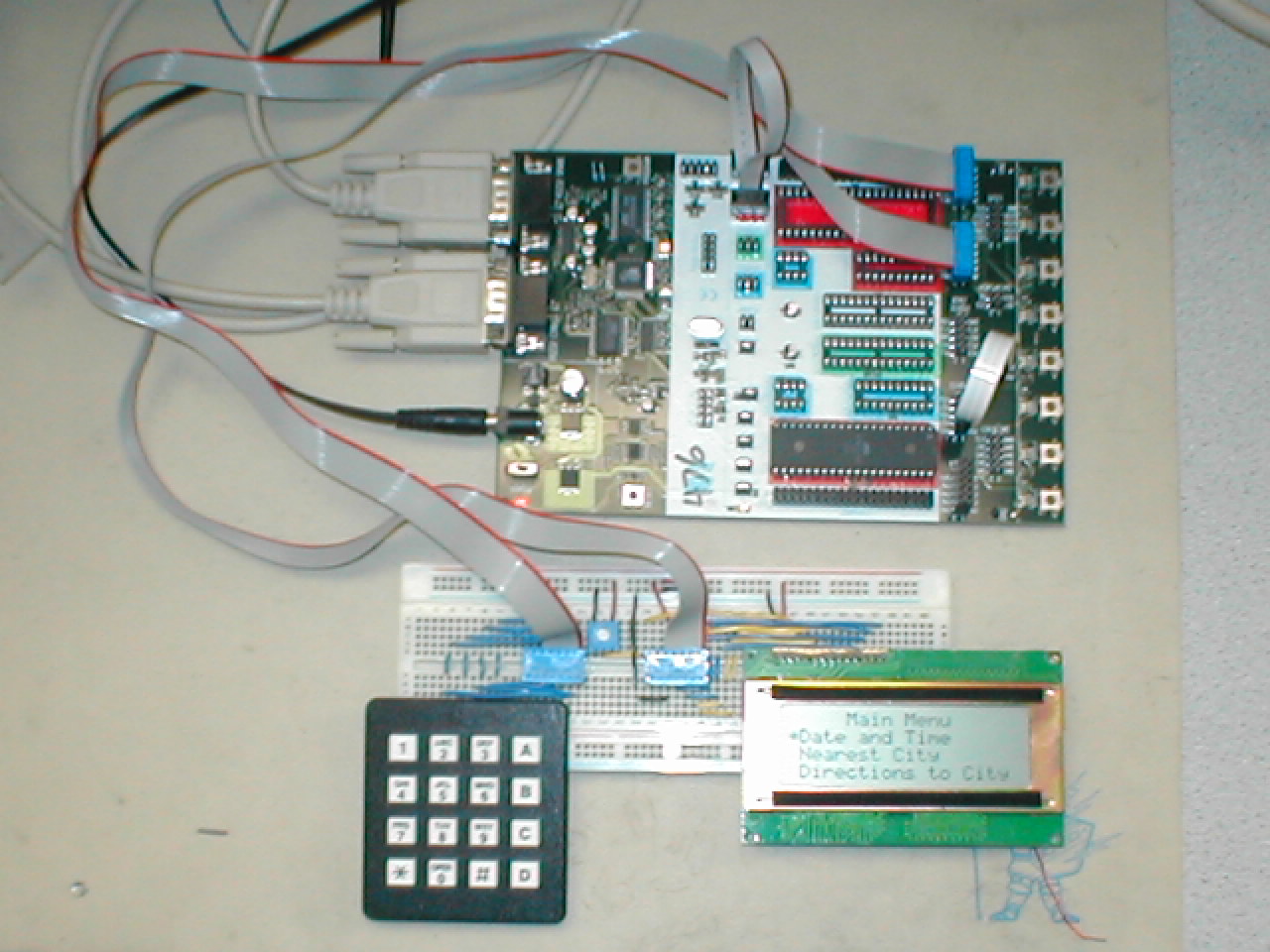
1 Atmel Mega163 microcontroller chip
1 Atmel STK500 development board
1 4x4 keypad
1 Optrex DMC-20434 4x20 character LCD
1 breadboard
(optional) 1 GPS receiver (or simulator) capable of outputting NMEA v0183 RMC sentences via RS232 connection


A picture of our hardware configuration:

Keypad
The keypad connected to the MCU was a 16-button keypad that consists of 8 pins that are used to decode a button push. These pins are connected to PORTB of the MCU in the manner specified below. When a button is pushed, only one pin on the keypad is high from Pins 1-4 and one pin is high from Pins 5-8. Based on this specification, we store a table of values (keytbl) that correspond to valid PORTB values. The numbers stored in this table correspond to only 1 pin being high for PORTB Pins 0-3 and only 1 pin being high for PORTB Pins 4-7. What we do to read a keypad button push is to first read the lower nibble of the button push and then the upper nibble of the button push. We do this by driving the upper nibble as output and reading the lower nibble as input, followed by driving the lower nibble as output and reading the upper nibble as input. By using this scheme, if a button is pushed, only 1 pin will be high in the lower nibble and 1 pin will be high in the upper nibble. We use this scheme to decode the numbers by looking them up in the keytbl and storing these keytbl values as the sequence of button pushes entered by the user.

The scheme that we used to convert the keypad button push to formatted ASCII was to write a function keypad_to_char that converted keypad values to ASCII characters. It would take in a keytbl value and perform a switch on this value. Based on which keypad value it was, it would return a different character.

On the keypad, the A button corresponded to the scroll-up button, the B button corresponded to the scroll-down button, the C button corresponded to the backspace button, and the D button corresponded to the select/enter button. The Pound and Star buttons were not used. The numerical buttons were used to input numbers for coordinates, time, or date.

LCD
The LCD used was an Optrex DMC-20434 4x20 character display. It was connected to PORTC of the MCU in the manner specified below.

UART
If NMEA mode is enabled, a GPS receiver/simulator must be connected to the UART port on the STK500 board with the following settings:

4800 BAUD
8 Data Bits
1 Stop Bit
No Parity
No Flow Control

The following is a schematic of the hardware used: