WAVEFORM OF CONTROLLER
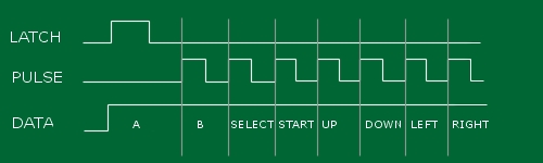
Nintendo Controller Pin Out:
                          +---+
                 GND ---> | o  \
                 LATCH -> | o o + <-- +5Vdc
                 CLOCK -> | o o | <-- N/C
                 DATA --> | o o | <-- N/C
                          +-----+
THE LCD:
We're using the Hyundai HG25504NG-01 with an SED1330F controller.
Pin Out:
               PIN| VAR | Description
                --------------------------------
                 1 FG    GND
                 2 VSS   GND
                 3 VDD   +5V
                 4 V0    Variable (low is higher contrast)
                 5 /RES  Reset
                 6 /RD   Read
                 7 /WR   Write
                 8 /CS   Chip Select
                 9 A0    Data Type Select
                 10 DB0  Data Display Bit 0
                 11 DB1  Data Display Bit 1
                 12 DB2  Data Display Bit 2
                 13 DB2  Data Display Bit 3
                 14 DB2  Data Display Bit 4
                 15 DB2  Data Display Bit 5
                 16 DB2  Data Display Bit 6
                 17 DB2  Data Display Bit 7
Initialize Sequence:
Bit:                [7 6 5 4 3 2 1 0 ]
                 -------------------------------
                 C  [0  1 0  0  0  0  0  0 ]
                 P1 [0  1 IV 1 W/S M2 M1 M0]
                 P2 [WF 0 0  0 |<---FX--->|]
                 P3 [0  0 0  0 |<---FY--->|]
                 P4 [|<-------C/R-------->|]
                 P5 [|<-------TC/R------->|]
                 P6 [|<-------L/F-------->|]
                 P7 [|<-------APL-------->|]
                 P8 [|<-------APH-------->|]
The LCD contrast voltage actually changes depending on
what mode the LCD is in (the LCD has 3 modes: Text, Graphics, and Text and Graphics).
We used the Text and Graphics mode, requiring a contrast (V0) voltage of ~-11.25 V.
Originally we thought that this could pose a problem because the max voltage on
V0 is such that Vcc - V0 = +15V, or that V0 can range to -20V. Fortunately this
voltage was easily obtained using the ECE 232 Protoboard setup.