![]() Driving the stepper motors
Driving the stepper motors
Each stepper motor has six
wires coming out of it: two brown wires and blue, orange, white and red wires.
In order to drive the motor the brown wires need be connected to the power
supply and the other four have to be excited in sequence. In order to find the
appropriate voltage for the power supply, we found out that the stepper motors
work properly with voltages above DC 8 volts and since we preferred for the
motors not to get very hot, we used DC 12 volts as the power supply for the
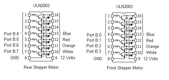
motors. To drive the stepper motors with appropriate voltage, we used TIP31C
NPN configured as in ULN 2003 IC, figure below.
![]() Stamping
Stamping
In order to stamp, we used two
solenoids to have enough power to put the stamp on the envelope and then bring
the stamp to its initial position as quick as possible. The proper power was
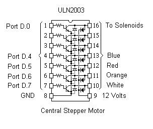
achieved when exciting the stamp with 10.5 - 12 V DC. For this application we also used the same driving system
as we used for the stepper motors. (As in ULN 2003)
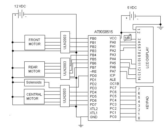
![]() Control System
Control System
The brain of the system is
the Atmel 8515 micro-controller. The stepper motors, LCD, keypad and the stamps
are connected to input/output ports of the MCU. The schematic of the circuit
and connections is as in below figure.
![]() User-interface
User-interface
The user interface was done
through an LCD and a keypad connected to PORT A and PORT C of the MCU
respectively. The schematic of the connections is as below.