 By Zhi-Hern Loh
![]()
|
|
|
The hardware on this page was driven by the programs on the program design page. Hardware designPictures - Taken to document the process of the project. This section contains the following:
Part list
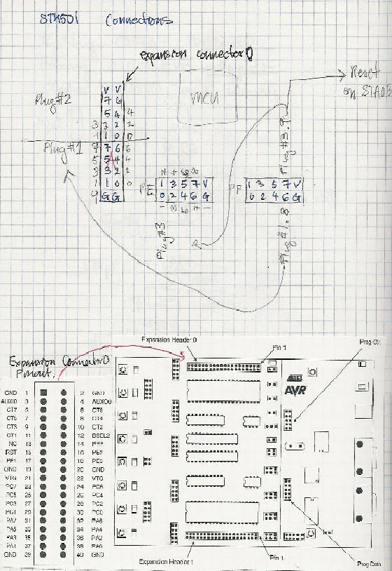
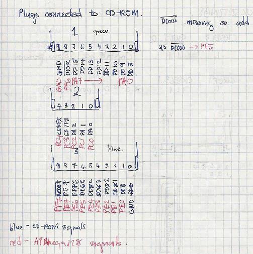
Port ListingsThere are two sets of port lists, the first set is the port lists used in the final version of the project. The second set is the port list designed for the CD-ROM version of this project.

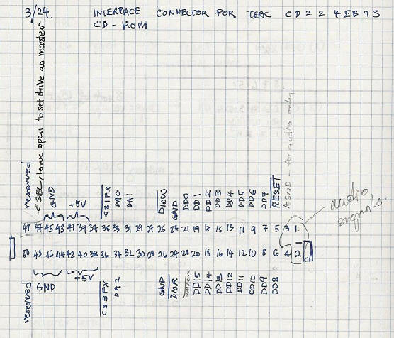
Schematic 1 - LCD contrast control. CD-ROM interface design and port listsThe CD-ROM drive that I started with was a TEAC CD224EB93. It had a Japan Aeronautics Engineering (JAE) connector (JAE-KX14/15). Unfortunately, the connector does not have a wire adapter and I had to solder a wire to it manually. This connector had 0.8mm spacing and soldering 30 wires to it was a nightmare. The soldering took up much of my spring break.
Schematic 2 - CD-ROM interface (part a)
| ||||||||||||||||||||||||||||||||||||||||||||||||||||||||||||||||||||||||||||||||||||||||||||||||||||||||||||||||||||||||||||||||||||||||||||||||||||||
|
Max1840 #1 |
Max1840 #2 |
||||
| Max1840 | |||||
| Function | Pin # | Function | Pin# | Function | Pin# |
| I/O | 10 | SDA I2C | 3 | DATA_REQ | 28 |
| Vcc | 9 |
3V |
|||
| CLK | 8 | SCL I2C | 4 | SCKR | 6 |
| RST | 7 | !Reset | 26 | SDI | 5 |
| GND | 6 |
GND |
|||
|
MCU |
|||||
| !Shutdn | 5 | 5V | |||
| Rin | 4 | !Reset | PF.7 | SDI | PD.7 |
| Cin | 3 | SCL(TWI1) | PD.0 | SCKR | PD.6 |
| DVcc | 2 | 5V | |||
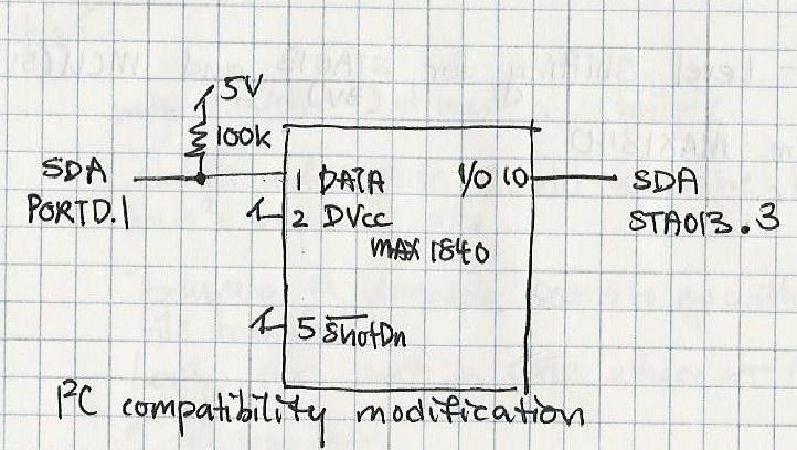
| Data | 1 | SDA(TWI1) | PD.1 | DATA_REQ | PD.5 |
Table 1. Port connections for the MCU and STA013 Interface
TWI1: Two wire interface. ATMEL documentation refers to the I2C functions for the Mega128 as TWI.
There was another MAXIM part (MAX 3370) that was made specifically for I2C level shifting. However this part only had two input and output lines which was insufficient for my use. (Click here for a picture of my work on the MAX3370).
|
|