ECE
476 Final Project
Spring 2002
Gmouse
Christopher
W. Kung (cwk7@cornell.edu)
Peter Wang (pw33@cornell.edu)
Introduction
With all focus of computer technology advancement placed on processors and memory, sometimes the most simple of components are overlooked. This is especially the case with the mouse, a device that has changed very little since its conception by Xerox. It still retains its basic shape and function in moving a cursor within a graphical user interface for users to easily and effectively use their computers. Although the interface of the mouse to the computer has changed a numerous of time (serial, PS2, USB, etc), the actual mechanics of the mouse has undergone only about two changes in 2 decades! There originally was the classic ball mouse that turned wheels to indicate movement. Recently, optical mice that used cameras to detect changes in the surface at you moved the mouse have become more and more popular. Although the shape and ergonomics of a mouse has changed over the years, the interaction to the mouse has not changed.
Our project attempts to break the traditional mouse mold by taking a completely different approach of how a person uses a mouse to interact with his or her computer. We attempt to design and implement a mouse that senses and determines movement using an Analog devices ADXL202AE accelerometer and some human ingenuity with hand movements. We idealize this mouse as a ring that a person can put around his finger, and either by turning their wrists or pointing up and down, the person will be able to interact with their mouse cursor. The ring will have integrated buttons for left/right click and to turn off movement detection so that the mouse pointer will not become jittery as a person types or handles other tasks. Another ideal packaging for the mouse could be in a shape of a ball, and the user simple rotates and twists the ball to move the cursor.
High Level Design
The accelerometer is interfaced with the STK200 board running the Atmel ATMEGA163 microcontroller chip. The accelerometer was soldered onto a custom PCB and the analog outputs were tapped for analog to digital conversion. The circuit board looks as follows.
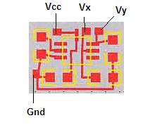
The accelerometer is capable of determining 2 axes of acceleration, so we programmed the MEGA163 to perform the ADC of the 2 analog outputs from the accelerometer and format that data to conform to the 3-byte Microsoft standard for RS232 serial communications. The 3-byte data packet Microsoft standard is given as the following:
D7 D6
D5 D4
D3 D2
D1 D0
1. 1
1
LB RB
Y7 Y6
X7 X6
2.
1
0
X5 X4
X3 X2
X1 X0
3. 1
0
Y5 Y4
Y3 Y2
Y1 Y0
The first byte of this 3-byte packet denotes the synchronization byte that allows the windows serial mouse driver to know that this byte and the following 2 bytes represent mouse location information. LB and RB stand for left button and right button respectively, and they are high if pressed and low if not pressed. X and Y represent the change in the mouse coordinates using eight bits, with 7 being the most significant and 0 being the least significant. The software driver determines the absolute position of the mouse and the mouse only needs to transmit the change in position. The driver uses that information to calculate the new absolute position on the screen. The position information is a byte-wide signed integer ranging from -127 to +127 in both the X and Y axis. The larger the number on X and Y, the larger the change on screen of the mouse cursor.
In order for our mouse to be detected by Windows as a Microsoft Serial Mouse, the software needed to detect the toggling of the RTS line. The following shows the pin out of the serial port:
9 pin Wire Name Comments
shell
Protective Ground
3
TD
Serial data from host to mouse (only for power)
2
RD
Serial data from mouse to host
7
RTS
Positive voltage to mouse and reset/detection
8 CTS
6 DSR
5
Signal Ground
4
DTR
Positive voltage to mouse and reset/detection
DTR = Data Transmit Ready, RTS = Request To Send, DSR = Data Set Ready, CTS = Clear To Send
When Windows tries to detect for new hardware on the serial port, it would toggle the DTR and RTS lines in synchronous. In order for a serial mouse to be detected, it needs to respond with an ASCII "M" or 0x4d in hexadecimal. The RTS line would toggle 3 times, and the mouse would need to respond with the ASCII ‘M’ each time RTS toggles in order to Windows to confirm that a Microsoft Serial Mouse has been detected. Once the mouse is successfully detected, DTR and RTS go high to +7 V and these lines can power the on-board microcontroller of a serial mouse. Since our mouse is powered by the STK200 board, the RTS line was cut and fed into an input port for detection. The RS232 port is set to a speed of 1200 bps and sends 7 data bits with 1 stop-bit for proper communication.
Hardware Design
We used the ADXL202AE accelerometer from Analog Devices. This accelerometer is a MEMS device and is capable of outputting both a digital pulse width modulated signal and an analog signal. The pulse width modulated signal has 2 components, the total time, t2 and the acceleration time, t1 whose width is dependent upon how much acceleration is experienced by the sensor. The analog output produces a level voltage of 2.5V when the accelerometer is not tilted and varies as the accelerometer is moved. For the project, we only used the analog voltage outputs to update the mouse position. The following picture shows the pinout of the accelerometer.
In order to properly interface the accelerometer with the STK200, the following circuit needed to be built in order to clean, impedance match, and format the signal to be within range of the 8-bit ADC. The analog output of the accelerometer is at a nominal 2.5V on level ground and shifts up to 3 V and down to 2V when moved. The analog port was used to handle the analog accelerometer outputs. The following pictures show the circuit diagram used for each analog output.
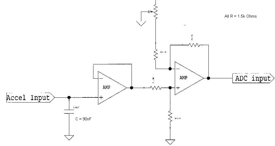
The 90 nF capacitor is used to clean the signal and set a 10 Hz bandwidth for the accelerometer. The Op-Amps used is the LM3410 from National Semiconductor. The first Op-Amp is used for impedance matching in order for the signal to be strong enough for reading. The second Op-Amp circuit is used as a subtractor circuit that subtracts 1.25V from the nominal to guarantee that the input voltage is within the 8-bit ADC range. The reference voltage comes from a potentiometer that set the voltage that is to be subtracted from the input.
Since our design needed to tap the RTS line to sense for toggling, we created a circuit that will protect the port pins from voltage overload since the RTS line ranges from -7V to 7V. The following circuit diagram shows how it was made:

The diode that is tied between output and VCC ensures that a voltage above Vcc is passed and held at Vcc. Likewise, the other diode that is tied between the output and ground is to set any voltages below ground to ground. This results in a 0-5V operating range which is suitable for the input pins. RTS is tapped on port C, pin 0.
The STK200 board uses an RS232 serial communications port to communicate with the host computer.
In order to emulate the mouse buttons, a push-button pack with 4 buttons was used with 3 of the buttons hooked to pin 0, 2 and 4 on Port B. An interrupt driven software state machine was used to debounce the buttons. The buttons consisted of a left button, right button and kill mouse button. The kill mouse button is used to disable the mouse at a push of a button and likewise, re-enable the mouse for use again. This feature is so that the user can type while wearing the mouse and not have the pointer moving randomly due to the typing movements.
Software Design
The microcontroller code was developed using the AVR CodeVision Development software and is written in C. The program consisted of 2 tasks and uses 3 different kinds of interrupts.
The analog to digital conversion of the accelerometer voltage is performed by the ADC_INT interrupt. This interrupt triggers each time the CPU sleep command is executed. This command is issued by the assembly instruction sleep. When the ADC is triggered, the CPU is turned off and the program execution pauses while the ADC hardware performs the conversion. The CPU is put to sleep to reduce switching noise that may interfere with the ADC. Once the conversion is completed, the CPU is brought back by the ADC_INT interrupt and the ADCH register contains the 8-bit conversion value. This conversion is done twice to record the voltage of the x and y axes of the accelerometer.
External interrupt 0 is set to trigger on the rising edge of a signal fed into PORT D, pin 2. This was used to in order to get our mouse to be detected as Microsoft Serial Mouse. When Windows searches for new hardware on the serial port, it would toggle the RTS line and poll for any response from any device that is connected to the serial port. In order for our mouse to be detected as a Microsoft Serial Mouse, the mouse needs to be see this toggling of the RTS line and respond with an ASCII "M" or 0x4D. Each time the interrupt is triggered, code was used to test for the toggling of the pin. Once toggled, the mouse would respond with the ASCII M and do that for 15 times. Once that is done, the mouse is fully enabled and Windows fully recognizes the component as a mouse and will accept the serial input as a mouse and process the inputs as such.
The timer 0 interrupt is used to sequence two tasks, task1 and task2. The pre-scalar for timer 0 is set to 64 and the reload value is 256-63 to have the interrupt trigger at 1 ms. Two variables, time1 and time2, indicate how often task1 and task2 should execute. Each time the interrupt is triggered, time1 and time2 are decremented by 1. The main while loop monitors time1 and time2, and when their value reaches zero, their respectively task is executed. The time for t1 is set to 1 and the time for t2 is set to 10, indicating that task1 executes every 1 ms and task2 executes every 10 ms.
Task1 is responsible for debouncing the button presses from the push-button pack. The debounce state machine contains 5 states, ready, almost-ready, but_press, but_release1 and but_release2. The following diagram shows the state-transition table:
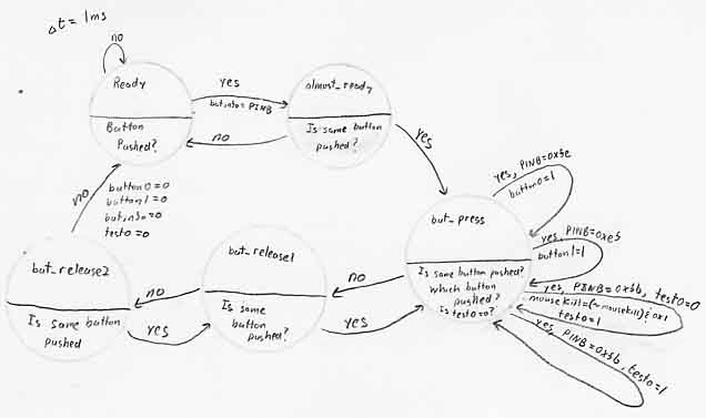
Once the button press is recognized, that information is outputted to task2 for output to host computer. This is to accommodate the use of clicking and dragging feature of the mouse. In order for the mouse to be able to drag a window, the button information needs to be decoded before the button is released to accommodate button hold. The button debouncing state machine debounces left click, right-click and mouse kill.
Task 2 contains the code that samples the accelerometer output, reads the ADC output of the accelerometer signal, and processes the data into the Microsoft 3-byte data packet for output to the host computer. The X and Y information from the accelerometer is read successively by setting the ADMUX to poll the different inputs and putting the processor to sleep to perform the ADC. Once the 2 results are known, an if statement determines if this is the first reading ever done. If so, the 2 values read will be labeled as the offset and subtracted from later ADC results as a means of offsetting the accelerometer to the 0 position of no movement. After which, the results are tested to determine if they are within the -3 to +3 range, if so, the value is set to 0. This will ensure a buffer range where the mouse will not move. This takes into account any noise coming from the accelerometer. The final X and Y values are then formatted to the Microsoft 3-byte data pack standard for output. The bytes are sent out one by one by writing to the UDR. Task2 is clocked at 10 ms.
Results
This project was a success! Windows was able to detect the mouse as a serial mouse, load the appropriate driver for it, and allow our project to pass data to move the course. The movement of the mouse pointer is smooth and accurate. This mouse does take some getting use to because it operates more like a joystick. However, it turns out that the mouse is very low impact since it only requires the user to tilt his/her wrist. This is unlike any other mousing device since it requires the user to move his/her and also requires the hand to be at a certain position. The usability demonstration is done by taping the mouse to the bottom of a mug! This interface allows the user to sit back, relax and how the mug the way it’s normally held and move the mouse just by tilting his/her wrist. This mouse does work!
Future Plans
With more time and resources, we idealize that the mouse can be packaged in a ball-shaped shell and communicate via a RF transmitter/receiver pair to transmit data to a base station. Again, the user would just hold the ball as he/she would any other ball and tilt their hand to move the mouse.
Appendix