The hard drive is controlled by writing and reading to a series of registers that are addressed by the address select and chip select lines. Data is read or written off of the data bus corresponding to a pulse given on the read or write line. Instructions are executed by filling the registers with the parameters of that instruction and then writing the correct bit sequence to the command register. The state of the hard drive is monitored by polling the status or alternate status register.
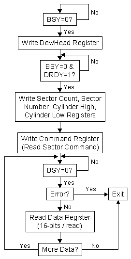
For our project, we implemented only the read sector command. This instruction requires a sector address which can be provided in either LBA or CHS (cylinder, head, sector) format. We chose to use LBA mode in which every sector is numbered consectutively from 0 because it is consistent regardless of the number of heads per cylinder or sectors per track. Also, all of the sector information stored in the file allocation table (FAT) on the disk is also in this format. The LBA address is a 28-bit quanitity and is loaded into the device/head, cylinder high, cylinder low, and sector number registers, making sure to set the LBA bit in the device/head register. We chose to only read one sector at a time so sector count was always set to 1 since one sector is 512 bytes and the mega163 has only 1KB of memory. The algorithm for interfacing with the hard drive is shown in the figure below. The BSY, DRDY, and ERR bits are found in the status register.

Upon power up the slave MCU requests the sector 0 of the hard drive which contains the partition records of the different partions on the drive (only one in this case). This data structure gives the LBA address of the start of the partition which is also the location of the boot sector, this is the next sector requested from the disk. The boot sector structure contains the bios parameter block which gives the cluster (one cluster equals 4KB or 8 sectors in FAT32) of the root directory The formula shown below is used to convert the root cluster to a sector address (all parameters used below are also found in the bios parameter block).
FirstDataSector = ReservedSectorCount + (NumberFATs * FATSize) + BootSector
X_Sector = (X_Cluster - 2) * SectorsPerCluster + FirstDataSector
Located at the root sector are a consecutive list of directory entry structures that contain information about the files in the root directory. The master MCU filters through all the files and records only those with ROM extensions. The most important attributes of these files are the name, size, and starting cluster (formula above is used again to convert from cluster to sector) which are stored in an array in memory to aid in servicing requests by the master MCU.
For simplicity, we limited the number of files to eight since each directory structure is 64 bytes and 8 of these equal one sector. Additionally the size of a file was restricted to 4K so that the size of a file does not exceed a cluster and we do not have to deal with lookups in the FAT.
The master MCU requests the files in the root directory from the slave at startup and enters a state machine to service button presses from the user. The state machine has a period of 25ms which is sufficient to debounce the buttons. The master cycles through the file names as the user presses the cycle button. When the program button is pressed, the index of the currently selected file is sent to the slave MCU. The contents of the file are read from disk by the slave and sent to the master.
In order to maintain synchronization between the master and slave during serial communication we created a simple request/receive protocol. When the master wants to request a byte from the slave, it first sends a dummy byte and then blocks while the receive complete flag is zero. On the slave side, when a byte needs to be sent, the MCU blocks until the receive complete flag is one (i.e. the dummy byte is received) and then actually sends the byte which terminates the blocking of master. This prevents a byte being sent unless the master has specifically requested it, thereby signifying it is ready to receive.
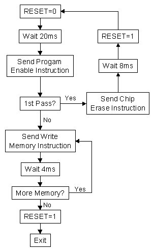
As mentioned in our high level design, as each line of the ROM file is received it is decoded from ascii to an integer and programmed into the flash of the target MCU. The master MCU utilizes serial downloading (described in the 8515 data sheet) to program each word in memory. The algorithm for programming the flash memory is shown in the figure below.
