ELECTRONICS
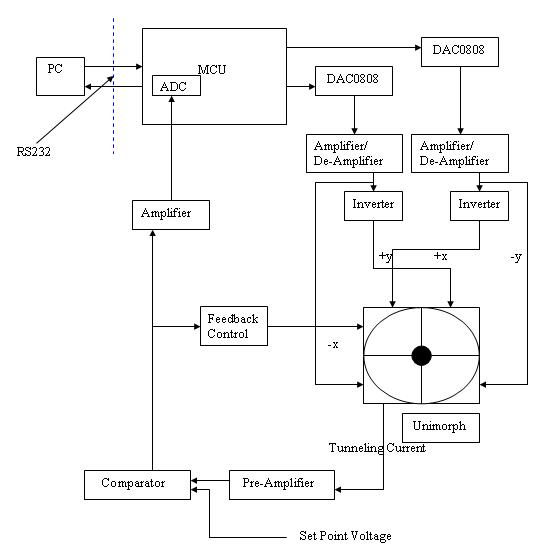
Block diagram of the hardware (excluding the filters)
The PC starts the operation of the STM by issuing commands to the MCU. In return, the MCU generates the appropriate x and y driver signals. These signals are converted to analog by a set of DAC0808s, and the outputs of the DACs are applied to the x/y terminals of the piezzo disk. The -x/-y terminals are connected to inverted versions of the DAC outputs.
The tunneling current flows from the tip attached to the unimorph to the pre-amplifier, which is a current-to-voltage op-amp amplifier with a gain of 108. The output is then subtracted from the set point voltage corresponding to the desired sample-tip separation. The result, when non-zero, indicates the difference between the set point distance and the actual sample-tip separation at the location being scanned. By amplifying this difference and sampling it with the ADC, the tunneling current is measured. The difference signal is also input to a feedback control circuit, which integrates its input to generate a voltage level that increases as the difference gets larger. This voltage is treated as the z-driver for the piezzo. Thus, the tip gets closer to the sample if the distance is larger then the set-point distance and moves away from the sample if the sample-tip separation is shorter than the set-point distance.
Various low-pass filters (not shown on the block diagram) were also used to minimize the noise level. The mechanical assembly was shorted to ground for 60Hz noise cancellation. For certain measurements requiring minimal noise (step sizes lower than 5nm), the entire circuitry was placed in a Faraday cage made out of aluminum foil.
Refer to the schematics section for the full circuitry.
MECHANICAL ASSEMBLY
The mechanical assembly consists of a vibration isolator and a metal piece for supporting the unimorph and doing the coarse adjustment of the tip. The vibration isolator basically acts as damped spring with a heavy mass attached to it. The metal piece has an adjustable knob that has a 5 micron/degree resolution.
To get the tip even closer to the surface after the coarse adjustment, a secondary piezzo is placed under the sample. By varying the voltage on this piezzo, it is possible to lift the sample up and down.