 mouse will start
generating the CLK after receiving RTS.
mouse will start
generating the CLK after receiving RTS.1) Codes that Interface with mouse.
Some background on interfacing with the mouse. We used [1] and [2] for information on how to interface with the PS/2 protocol.
· There are two signal lines between the mouse and the microcontroller. Data and Clock. Signal level is 0V or 5V.
·
When microcontroller want to put a line low, it
will set the corresponding PORT pin to output 0V to ground the line to 0V. When
microcontroller is not using the line, it will set the the PORT pin as input and
enable the on-chip pull-up resistor to supply a 5V to the line.
In our design, pin PA0 is the DATA, and pin PA1 is the CLOCK.
Each action of releasing the line or setting it low involve 2 steps. 1) set the
pin to input or output 2) enable pull-up resistor if pin is set to input.
We defined 4 macros in assembly to make the codes cleaner.
| Macro names | Line voltage | |
| DATALOW | DDRA.0=1 and PORTA.0=0 | DATA=0V (PA0 is set to output 1.) |
| RELDATA | DDRA.0=0 and PORTA.0=1 | DATA=5V (PA0 is set to input and pull-up resistor is enabled.) |
| CLKLOW | DDRA.1=1 and PORTA.1=0 | CLK=0V (PA1 is set to output 1.) |
| RELCLK | DDRA.1=0 and PORTA.1=1 | CLK=5V (PA1 is set to input and pull-up resistor is enabled.) |
· The mouse generate the clock at a frequency in the range of 10-16.7Khz. The mouse release the line when it is not sending or reading data. It will start oscillating the CLK when it want to send or read data. The microcontroller can pull the CLK line low at any time to inhibit the mouse from sending data. Data that was not tranmitted successfully will be transmitted at the next available time.
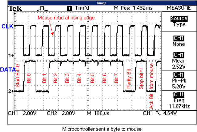
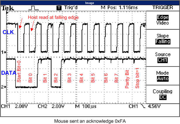
· For each byte of data, the data consists of 1 start bit, 8 data bits (Least significant bit first) , 1 parity bit (odd), and 1 stop bit. Start bit is always 0 and stop bit is always 1. If the byte is sent from microcontroller to the mouse, the mouse will give an acknowledge by pulling both the DATA and CLK low.
· Microcontroller read data at falling edge and mouse read data at rising edge. This means microcontroller will need to put each bit on the DATA line before the rising edge for the mouse to read. To read a bit from the DATA line, the microcontroller just need to read at every falling edge.
· Microcontroller need to send a Request To Send (RTS) to mouse before sending any data to the mouse. The mouse will acknowledge with a byte (usually 0xFA) and start generating the clock.
· To send an RTS, the microcontroller need to pull the CLK low for at least 100ms, follow by pulling the DATA low and then release the CLK.
mouse will start
generating the CLK after receiving RTS.
· There are 4 modes that the mouse can operate [1]. In the remote mode, the mouse only sends data upon request from the host. We used this mode in our program. The microcontroller sends 0xF0 to mouse to instruct it to go into remote mode. The mouse will response with 0xFA if it received the request successfully and has no problem to go into remote mode.
· When the mouse is operating in the remote mode, the microcontroller requests data from the mouse by sending 0xEB, and the mouse will acknowledge with 0xFA. 3 bytes of data is sent from the mouse in the following clock cycles.
· The 3 bytes of data requested from the mouse in the remote mode is of the following format.
| Bit 7 | Bit 6 | Bit 5 | Bit 4 | Bit 3 | Bit 2 | Bit 1 | Bit 0 | |
| Byte 1 | Y Overflow | X Overflow | Y Sign bit | X Sign bit | Always 1 | Left Click | Middle Click | Right Click |
| Byte 2 | X Movement | |||||||
| Byte 3 | Y Movement | |||||||
· To reset the mouse, the microcontroller send 0xFF to the mouse, and the mouse will acknowledge by sending 0xFA.
· The microcontroller always start with RESET (0xFF), Set remote mode (0xF0), and then request data from mouse with 0xEB periodically.
The two figures below show a snapshot of the signal when a byte is sent by the microcontroller and by the mouse.
Two functions (mouse_send( ) and mouse_read( ) ) were written to transfer a byte of data between the microcontroller and the mouse. The program actively request data from the mouse whenever it has free time.