Our ECE476 Final Project is a digital pre-amplifier. A digital pre-amplifier basically takes an analog music signal, converts it digitally, and spits it out as a new, modified, analog signal. Our decision to do this project was sparked by our interest in music and electronic equipment. High-end receivers and amplifiers often use this analog to digital, digital back to analog conversion scheme along with Digital Signal Processing (DSP) to modify music signals. To understand, and possibly replicate how many high-end receivers work would be very exciting. Additionally, this project relates to a few of the design courses we have taken here at Cornell University, which include Power Switching circuits and DSP.
DSP is basically a substitute to analog filtering by using digital calculations sampled analog values. You can implement a digital filter using the following generic transfer function where n is the order of the filter and 'b' and 'a' are coefficients corresponding to the weights in the difference equation.
The above transfer function translates into the following equation for our music manipulation. In our calculation, S(t) is the sampled voltage. As an example, S(0) is the sampled voltage at the current time, S(-1) is the previously sampled voltage, S(-2) is the 2 sampled voltages prior etc. V(t) is the voltage output after digital filtering has been accomplished. Like S(t), we must also store these V(t) values since they will be used in future digital filter calculations. The equation below depicts a filter with an order of 2, but the equation can be expanded or contracted based on the filter order you are using.
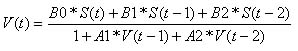
It is easy to see that this is an Infinite Impulse response filter (IIR). An IIR filter takes previous inputs and outputs, and the current input, to calculate the new filtered output. As the name suggests, each new output is affected by an infinite amount of previous inputs (each input affects the next input, which affects the next input and so on).
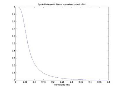
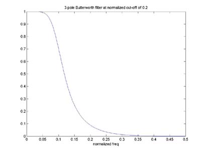
Finally, we obtained the coefficients for the transfer function using MatLab. We decided to use Butterworth type filters, which are know for their relatively flat pass and stop bands. Other filters we could have implemented include the Chebychev filters, which have a characteristically fast roll-off frequency but more ripple in the pass band or stop band. Using the MatLab command [b,a] = butter(2,0.2), we obtained the coefficients to our transfer function. The first parameter in 'butter' refers to the order of the filter; the second parameter indicates a cut-off frequency at defined certain percentage of � the sampling frequency.
Analog FilteringAlso part of our project was Analog Filtering. A simple Resistor Capacitor circuit will create an analog low pass filter. To evaluate the low pass filter, simply calculate the time constant (T = R*C). The break frequency of this low pass filter is calculated by
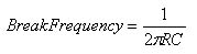
Simple filters like this are useful in filtering high frequency outputs associated with our PWM output.
PWMA pulse width modulator outputs a uniform frequency square wave with a varying duty cycle. The Duty cycle refers to how long the waveform is high compared to when it is low. Altering this duty cycle is what creates the Digital to Analog conversion feature of the PWM. If you average this duty cycle, the result is an analog waveform that spans from VCC to Ground (or what ever else the PWM waveform swings to).
END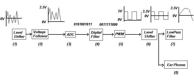
In order for our circuit to adequately sample an analog music signal using its on chip ADC, we first level shift the music from a 0V mean to roughly a 1.25V mean (the ADC samples voltages ranging from 0V to 2.5V). We accomplish this by using a simple resistor divider and a 4.7uF capacitor to block DC voltages ( refer to #1 on the flow diagram above). With a VCC of 5V, a 100K resistor and a 330K resistor provide a new music mean voltage of 1.16V.
The output of the voltage shifter is fed into a voltage follower (comprised of a LM7111 op-amp) (#2) so the noise and impedance associated with the resistor divider does not interfere with the measurements taken by the ADC. By changing the volume from the source of our music, we are able to extend the range of the music until it reaches roughly a 0 to 2.5V peak-to-peak, which is optimal for the ADC.
The on board ADC (#3) samples the music at an optimal speed of 8.92kHz. There were various design considerations when choosing the set up for the ADC. Not to exceed the accurate operating range of the ADC, we made sure the ADC clock was below 200kHz. With a prescaler of 128 using a 16MHz clock, our ADC clock speed is 125kHz. Additionally, we wanted 10-bit resolution on the ADC (instead of 8-bit resolution - a couple cycles faster per conversion) to ensure that we would are running DSP calculations on the most accurate music samples obtainable.
After the ADC, we manipulate the digitally converted voltages by using an IIR filter. Constructing 1,2, and 3-pole Butterworth filters at various cutoff frequencies we simply use the microcontroller to run the DSP calculations on our 10-bit music samples (#4). Unfortunately, these DSP calculations are very intense and require numerous multiplications (3 for the 1 pole filters, 5 for the 2 pole filters, and 7 for the 3 pole filters). Since a full iteration of our code is required before the next sample can be taken, the CPU intense DSP calculations affect our sampling rate. To see how each filter affects our sampling rate, please see table 1.
The on board DAC (#5) blasts out the digitally modified voltages using a PWM. Like the ADC, this PWM has multiple settings. We wanted this PWM to oscillate at the fastest rate possible. A PWM works from an averaging of its duty cycle. The more cycles you have in a certain time period or 'musical burst,' the better averaging you can obtain. Therefore, we set the PWM prescaler to 1, and also used the 8-bit resolution for a maximum PWM operation speed. We felt that the 10-bit resolution was too slow (4 time slower than the 8-bit) to justify the extra resolution in a PWM that was going to be averaged anyways. The PWM frequency at an 8-bit resolution is 31,250 kHz. Assuming we need approximately 10 PWM cycles to accurately represent a music oscillation, we can reproduce music frequencies up to 3.1 kHz.
Since the PWM operates from VCC to ground, we need to re-center the PWM waveform back to a 0V mean. This is accomplished by another simple voltage shifter circuit (#6) comprised of two 100K resistors, a 2.2uF capacitor and 5V and -5V power supply.
From this signal, we had a couple ways to evaluate the music output. One method was to filter the PWM, basically average the square wave output into an actual analog signal using a simple low pass filter (#7). We accomplished this with a 10K resistor and a 0.01uF capacitor. Unfortunately, this would in itself provide filtering when one of the goals of the project was to evaluate the effects on DSP to our music. Thus, we can tap directly into the PWM and listened to that using a small headphone (#8). The mechanics in the headphone would simulate an averaging of the PWM to our ear. Thus we are able to hear a less modified voltage output. Unfortunately, the earphone also has its drawbacks. Since it is small, it is better suited for high frequency response, not the low frequencies we are interested in for our filtering.
Hardware/ Software trade offThis project is a mix of both software and hardware. The software refers to the digital filter calculations while the hardware is mostly used for converting analog signals to digital or vice versa. However, there are many solutions to the problem of filtering. This type of filtering could have been accomplished in an all-analog solution using various resistors, capacitors and simple op-amps. An analog design would be more expensive depending on the complexity of filter you want to build, and would not allow for little variability in the design to alter characteristics such as the cut-off frequency of the low-pass filter.
Adding the digital aspect to music manipulation brings software into the picture. Software allows greater flexibility in manipulating the music. We were able to implement things like a music level display on the LEDs. Additionally, we added a switching function that allows the user to instantly change the filter being used for a better comparison between the two. On the flip side, converting between analog and digital and vice versa will introduce some error into the system. Furthermore, we are getting rid of some accuracy in the music when we convert to digital. In any digital conversion we need to quantify the levels in the music; it can be argued that an analog solution provides infinite resolution.
Software considerationAn effective filter takes many samples and performs DSP calculations before running an average of the values. Due to the lack of speed and processing power, we can only run one set of calculations per iteration and ignore averaging. We also need to sample without the use of interrupts because interrupts are called by the hardware, which is rather inaccurate. Instead, we rely on the microcontroller clock to get an accurate sampling rate.
Inside a continuously running while loop, we start the ADC conversion, save the two output registers into integer variables, and restart the conversion. During that time, the DSP calculations are performed and the output values are saved. Pressing the first seven buttons on the microcontroller changes the filters used. Going down the Table 1 in the Results section, sw0 allows an unfiltered output and sw6 allows an one-pole calculation with a cut- off frequency of 2.1 kHz. The added DSP calculation also slows down the sampling rate, causing noise and oscillations at each edge.
In order to display the output level of the PWM, we decided to use the microcontroller's LED via PORTC, which takes fewer cycles than the number needed to display on a LCD. The LED display is updated every 300th iteration because updating it every iteration would be too fast for the eye to comprehend and slow down the sampling speed. If the sw7 button is pressed, it turns the LED display on and off; when the LED display is bypassed, the program takes less CPU cycles to complete, allowing a cleaner sampling.
We allow some peak falloff similar to a Winamp feature. The top 8 bits of the PWM is saved in an integer, so we examine this value to quantify the output level. The maximum level is saved per iteration, and if the next value is higher than the current maximum level, the next value is saved. The maximum level is decremented every time the LED display is updated, causing that peak falloff.
Things we tried that did not workIn our first proposal, we wanted to create a spectrum analyzer that would analyze the different frequency components in a music signal and output them to an LCD screen. We realized that this feature was unobtainable since using DSP calculations to separate out the various frequencies would be too CPU intensive. Thus, we intended create digital amplifier where we would only have to implement 1 digital filter.
We also intended to use an off chip ADC to do the sampling. We thought that it would alleviate the microcontroler of having to periodically dedicate some instructions to ADC control. We also thought it was possible to obtain a fast sampling rate from an off chip ADC. However, we realized that it was the CPU computations that were the limiting factor in the sampling rate. Regardless of how fast our ADC could sample, we would not be able to use the samples at that faster rate due to CPU computations.
We also proposed to use an H-bridge connected to the PWM to drive a miniature speaker. However, we found that the H-bridge and the PWM did not work well together. We were getting loading effects from hooking up the H-bridge to the PWM as the output of the PWM looked very uncharacteristic of a square wave. Because of this, we weren't sure whether our music was distorted based on the H-bridge and speaker, or from something else in our circuit. We decided to focus our resources on the rest of the circuit before moving to additional features such as a power H-bridge.
We also wanted to use an LCD to display the music level for our output. We realized that sending commands to the LCD takes precious CPU time, especially when our CPU resources are being constantly used for DSP calculations. Furthermore, refreshing the LCD does not happen on every sample cycle. Therefore, when we do decide to refresh the LCD, we are adding extra instructions to the CPU and that particular sample takes significantly longer time to execute (up to 2 times longer). This made our sampling inconsistent. We decided to scrap the LCD level display idea for one that used the LEDs on the development board. Setting PORTC every cycle takes few CPU cycles.
ENDTable 1 shows the various filters we used. All the filters were taken using MatLabs 'butter' function. As our analysis shows, the sampling rate is dependent on the number of calculations required to implement a higher order digital filter. The 3rd order Butterworth filter takes the most computations and its sample rate is respectively the slowest at 3.3 kHz. The 2nd order Butterworth filter is also significantly slower (4.48kHz) than no digital filter (8.92kHz). Lastly, a one pole filter (7-8kHz) is also slower than the no filtering, but by a very small amount.
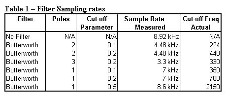
When we use no filter, the sampling rate is limited by hardware (the ADC sampling rate). When the CPU is being used for intense DSP calculations as it is in 2 and 3 pole filters, the sampling rate is limited by software. Electronics companies have gotten around these 2 problems by one, having very accurate and fast ADC to do the sampling, and two using specially designed DSP processors that have special instructions involving multiplications and additions that will speed up the calculations. Additionally, these designers could have used multiple processors to handle the various functions of the amplifier where we were stuck using one CPU for everything. Assigning certain tasks at other times would improve the sampling speed, and the timing between each sample.
Additionally, although we use a 10-bit resolution on our ADC, we only use an 8-bit resolution on the PWM output. Thus, the maximum number of music levels we can obtain is 2^8 = 256. This compares to the 24-bit ADC and DACs used by high-end electronics components. As you can see, our project is a very crude method to sample music, but the process and data flow involved is very similar to that of our receivers at home. Understanding the process behind the digital music sampling and not necessarily recreating its accuracy was a major focus to our project. Additionally, we were able to add features, such as music level displays and switchable digital filtering that wouldn't normally be found on any home receiver.
Wave Analysis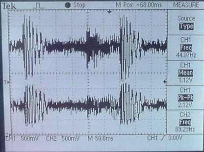 |
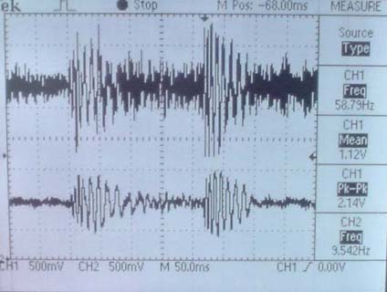
This printout shows the music input on the top and an unfiltered output ( Button 0 was pressed) on the bottom. Notice that the output lacks big spikes yet noise is still prevalent. |
 |
 |
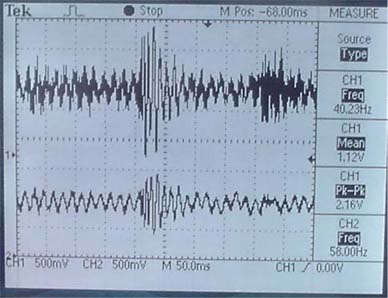
On the left is the wave output of the 2-pole low-pass filter design with a cutoff frequency at 224 Hz. However, there is still a significant amount of noise on the output, and this is apparent by how long it takes the frequency response to reach a magnitude of zero after the cutoff frequency.
 |
 |
This printout shows the output of a 3-Pole Butteworth low-pass design with a cut-off frequency of 330 Hz. This low-pass filter design was the best design compared to the others in this project because so much noise was eliminated from the original output while keeping the frequencies below the 330 Hz mark. This is evident by how much faster the frequency response reaches zero after the cutoff point than the 2-pole design.
ENDIn all, we were able to accurately reproduce music after converting it to digital bits. We were at first skeptical if this could be done as we weren't sure of a number of things. First of all, it was undetermined if an 8-bit resolution was good enough to accurately represent music. An 8-bit resolution translates into only 256 different levels of music.
Secondly, we were unsure of whether we were sampling fast enough to hear the important features that make distinguishable music. Nyquist's theorem states that you must sample at twice the frequency of the input in order to avoid aliasing. In other words, you have to sample fast enough so that the sampling can recognize all the details in the music. Sampling at too low a frequency will create extra noise at low frequencies from the high frequency elements. Since we sample at approximately 8 kHz, any frequencies above 4 kHz become noise. Music frequencies extend to roughly the 20 kHz range, but are not necessarily that strong at higher frequencies.
Finally, we were unsure if the PWM, oscillated fast enough to produce a well averaged output. At an oscillation rate of ~32kHz, the PWM could accurately output up to a 3.2 kHz signal (if 10 cycles are needed to create a well averaged output).
In the end, we found that although our Digital Pre-amp was not perfect in all these functions. However, we found that our components accomplished the tasks well enough to hear very recognizable music.
Digital FiltersIn evaluating the various Digital Filters, we found that there were a few that worked very well with our music. They seemed to genuinely filter out the higher frequencies keeping the low 'bass' frequency for the subwoofer output. The distinct low bass frequency is easily recognized with our LED display mechanism. Other digital filters, such as the 1 pole, 0.5 normalized freq, were superb at reducing noise in the music without getting rid of too much of the high frequency detail. Lastly we found some digital filters introduced a lot of distortion to the music almost to the point where it was unrecognizable. In the end, we concluded that the type of filter that produced the best output was based on user preference. There really is no 'right' filter to use for any one frequency. In many cases, that is great for audio products since they should allow for the user to tailor their system to their specific needs and preferences.
Things we could do differently next timeWe could invest in faster more accurate components, especially with the ADC and DAC. Additionally, since CPU computations were fairly intense, we may want to look into using 2 micro controllers, one dedicated only to DSP functions and the other to drive things like the display, and user interface. Another optimization that we could have done, but never looked into due to time constraints, would be optimizing filter calculations with assembly or C-code using integers instead of floating point numbers.
Intellectual considerationsAlthough we used sample code from last year's digital thermometer lab as a backbone for our code, everything is coded originally. This project aids in the understanding of digital music sampling, so there is nothing new and innovative in this design to be considered for a patent.
Ethical considerationsOur project was based on the idea that audio technology is something worth researching and experimenting with. Having previous DSP knowledge and a liking for music, we decided to research on filter design and analyzing audio signals. This goes along with point five of the IEEE Ethics Code since our project resulted in a deeper understanding in audio technology and its application. Throughout this project, we ran into problems and limitations in our design that led to changing our approach and modifying our design.
Also, as partners, we both had strengths and weaknesses in different aspects of electrical engineering. Therefore, to improve our technical competence (#6 of the Ethics Code), we helped each other with understanding areas of study where we were lacking and asked advice from teaching assistants about a topic we both do not fully understand.
During the planning of the design, we centered the output at zero volts to ensure that the signal is safe enough (#1) to export to a sound system. This avoids clipping from any DC offsets and prevents any possible equipment damage if a person simply hooks this circuit up to an amplifier without fully understanding its features.
As this project comes to a closure, we analyzed the results and concluded that the music signal does not sound clean because of the crude implementations of both the digital and analog low-pass filters. We also claim this circuit only efficiently produces low-passed frequencies because the slow ADC sampling frequency ideally only allows frequencies up to 1000 Hz to be sampled. These claims are consistent with Code 3 from the IEEE Ethics Codes. We like to thank Professor Bruce Land for directing us to some filtering techniques and helping us understand the specific details of the Atmel Mega32 microcontroller (#7). We also like to thank the TAs Paul and Andre for giving us input about our proposals.
END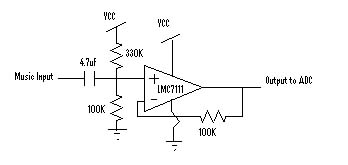 |
The input circuit consists of a level shifter (#1 of the flow diagram) which puts the DC offset at 1.16V and a voltage follower. This new shifted music signal is inputted to the ADC. |
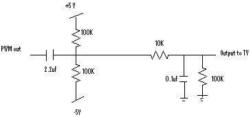 |
Since this circuit is a pre-amp, the output must be set at some safe and useful level. The PWM signal is offset at 2.5V, so it must be centered back to 0V. To solve this, a level shifter (#6) is used on the PWM signal, employing two identical resistors and a -5-to-+5 power supply to center the voltage back to zero. The PWM signal contains frequencies created from the 4kHz and higher sampling speed and other noises, we use a low-pass RC filter (#7) to get rid of them. The result is an output void of high noise frequencies. |
| Part Number | Description | Price | Company |
| TLC0838IN | Analog to Digital Converter | $3.08 | DigiKey |
| LMD18201T | H-bridge | $10.69 | DigiKey |