Hardware Design
Parts:
Amount Type
1 OpAmp LMC7111
1 10K Potentiometer
3 Visible LEDs (Yellow Green and Red)
1 7404/7400
4 330ohm
2 20Kohm
1 Infrared Detector
1 Infrared Emitter
Note: Emitter & Detector Radio Shack # 247-142
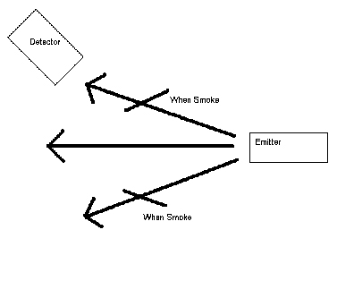
Typical smoke detectors use a phototransistor to detect the smoke in a room.
The detector that we backward engineered had an emitter and a transmitter for
a detection scheme working in the infrared wavelength. The emitter and detector
are set in a certain position that when smoke is present the light diffracts
from the smoke and the light is detected. For future reference this is the “A”
set up. A typical layout of this is shown below:
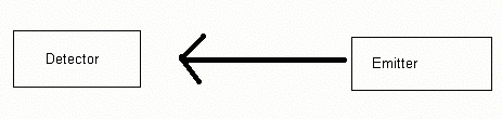
Another way to construct a smoke detector is to put the detector right across from the emitter and when smoke is present some of the signal from the emitter is diffracted and the signal becomes weaker. For future reference this is the “B” scheme.
Both ways of detection can be implemented by the circuit designed specifically for smoke detection. The circuit runs in 3 modes; Normal, Alarm, and Trouble mode.
Normal Mode: Green LED
A) No Infrared is detected
B) Infrared is detected
Alarm Mode: Red LED
A) Infrared detected
B) No infrared is detected
Trouble Mode: Yellow LED
A and B) Occurs when the detector breaks or is removed
The following is the circuit diagram:
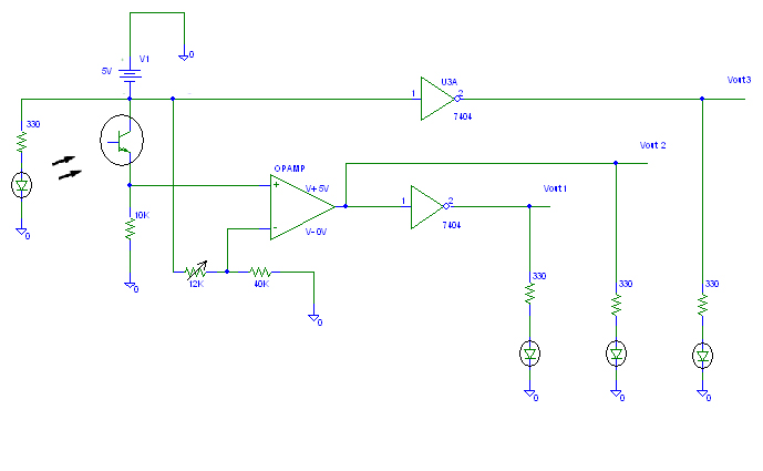
The LED to the left is an infrared emitting diode. The infrared is detected by the phototransistor and converted to a voltage. When first testing the phototransistor a 5 volt collector voltage was applied and an output at the emitter was measured. The measured output was close to 5 volts. If the infrared light from the sun is blocked from the phototransistor and a voltage close to 0 was measured.
The voltage just obtained by the infrared emitter at a distance of 3 centimeters length apart was around 2.1 volts. Varying the amount of exposure to the infrared detector we were able to detect a voltage of a volt when the detector should be tripped. This is when about half the single is transmitted and the other half is blocked by smoke.
To determine when to go from the normal state to alarm state an operation amplifier was implemented to work as a comparator. The input to the comparator is the phototransistors voltage at the emitter. This voltage to which the emitter is being compared to is at V- of the op amp. The output is either +5V, if the input is higher than the compare value, and 0V if it is smaller. The sensitivity of the detection is controlled by a potentiometer which changes the voltage at which the alarm changes state.
Depending on if scheme A or B is used while the normal LED is on the alarm LED is off and when the alarm LED is on the normal LED is off. To accomplish this from the one output from the op amp an inverter was used to invert the voltage and have it going to one of the status LEDS. The trouble output is taken from the infrared emitting diode to ground. If the detector is removed this would cause an open circuit. The LED turns on when this occurs.
For testing purposes both A and B schemes were implemented in lab and tested. A photo of the circuit is below:
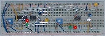
The clear looking bulb shaped parts are the phototransistors and the blue bulbs
are the emitters. Ideally the smoke detector structure would be built in a way
which enclosed the emitter and the detector but time constraints and wiring
issues made this a hard task to complete. Also, since we are not allowed to
start fires or smoke up the lab testing the alarm voltage cutoff for the phototransistor
was guess work rather than experimental. The potentiometers should be adjusted
in real world application to achieve the correct sensitivity.
The outputs of the detectors created in lab are inputs to the fire detection
software.