| |
HARDWARE DESIGN
|
| |
Laser Assembly
|
| |
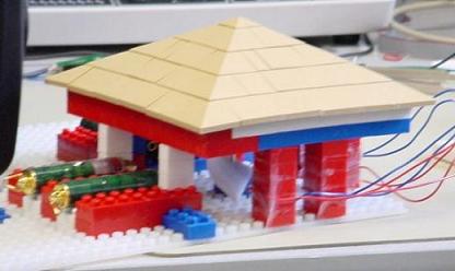
The laser assembly is an apparatus to determine wind direction by examining which of four laser beams are blocked by a windsock. The base of the device is Legos, which proved to be a convenient means of mounting all of the components. Tape was used to attach four laser pointers to Lego blocks, which were placed on the flat Lego base as shown in
Figure 1 on the Schematics page. Across from each laser beam, a PN158 phototransistor, with leads soldered to wires, was attached to a Lego post with tape. The phototransistors and lasers were adjusted so that the lasers hit the phototransistors directly. The phototransistor on/off state was monitored by measuring the voltage across the 680 Ohm emitter resistor in series with each phototransistor output. No comparator was necessary because the voltage across the resistor, regardless of ambient lighting, was always either less than 1V with the laser beam blocked or greater than 4.6V with the laser beam unblocked.
Power for the laser pointers was provided by three 1.5V LR44 batteries which were inserted into the laser pointers when the lasers were in use. The switch for the laser pointers was taped tightly to the “on” position. In the center of the device is the pen from a Victorinox Swiss Card running through some Legos and holding up a tissue “windsock.” A Lego roof was placed over the assembly to shield users from diffuse laser reflections. The laser assembly is shown below.
|
| |
 |
| |
Television Digital to Analog Converter (DAC)
|
| |
In order to get the proper voltages for the TV input, we connected two mcu output pins on port D (5 and 6) to a simple digital-to-analog converter, as displayed in Figure 2 on the Schematics page. The DAC provides voltages of 0V (video and sync both low, for sync pulses), 0.4V (video low and sync high, for black), 1.42V (video and sync both high, for white), and 1.02 (video high and sync low, unused). These values assume a diode drop of 0.6V. The values are a bit higher than ideal because a 100 Ω resistor to ground was used instead of 75 Ω in order to increase contrast. The DAC is connected to the yellow connector on the TV using an RCA phone jack. The TV should be set to video input.
|
| |
 |
| |
User Controls
|
| |
The switches (buttons) on the microcontroller board are connected to PortC. Initially we used PortB for the user inputs, but realized after a few weeks why buttons 6 and 7 appeared to need a debounce algorithm. It turns out that PortB pins 5, 6, and 7 are always connected to the programmer which often changes the Thevenin equivalence. As a result, we switched to using PortC but the problem was not fixed. Then, we realized there was a slight problem in our code and corrected it, leaving the switches connected to PortC.
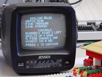
The user can move the rudder from far left, left, straight, right, or far right. The sail can be set to down, half sail, or full sail. The wind magnitude can be no wind, light wind, or high wind. The user also has the option to fire the cannon and view an overall map of the High Seas. The picture below shows the rules and controls game screen which state the rules and button functions. The user presses the buttons to adjust settings as follows:
- Button 1: Rudder Right
- Button 2: Rudder Left
- Button 3: Sail Up
- Button 4: Sail Down
- Button 5: Fire Cannon
- Button 6: View Overall Map
- Button 7: Increase Wind
- Button 8: Decrease Wind
|
| |
 |
| |
|