Program Code
The touchpad interface
Function: executecmd()
(Start)
Start by setting the ADB pin (C.0) on Port C as an input, and tri-stating it to an output. Float the data line to high, and clear registers to default values.
(Send command packet; calls sendcmd())
-(Attention Signal)
Set the line to low for about 800 usecs. If low time is greater than 824 usecs, then it’s a Reset Signal. The program starts over again, waiting for the line to be high.
-(Sync Signal)
The Sync Signal is sent by setting the line high for about 70 us between the rising edge of the Attention Signal and the falling edge of the first bit of the Command.
-(Command byte)
The MSB bit in the ADB command byte is sent first. This is achieved by calling a the putbyte routine, which sets the appropriate low time, and high time for a logic “0” or “1” bit. Each bit is 100 usecs. This is repeated until all 8-bits of the Command have been sent.
(Interpret the command)
All commands will be global and the default address will be 3 since we have only one relative position device. Determine whether it is a Talk, Listen, or Flush Command, and go to the specified Command routine. We implemented the talk and listen routine, but only use talk in the final version of the code.
(Receive data packet; calls getresp())
The talk command requires the MCU to wait for the line to go low. The time elapsed is the Stop-to-Start Time (Tlt). If this is a Talk Register 3 Command, the touchpad returns a random address as part of the two bytes sent to the Host. (In our results, bits 8-11 were random.) If this is a Talk Register 0 command, a response will occur only if there is data that needs to be sent. If so, the touchpad will send the data start bit (a ‘1’), two bytes of data from the indicated register, and a stop bit (a ‘0’ This signifies a successful transmission. If not, the program will revert back to the transmission of the Attention Signal.
(Send data; calls getarg() )
If the Command is a LISTEN Command, the MCU allots enough time to pass for the touchpad to interpret the command as such and then drives the line low after the appropriate Stop-to-Start Time. The MCU then starts sending the rest of the data packet with the start bit first, followed by the two data bytes, and then a stop bit. The touchpad should write this Data into the specified register.
Function: getresp()
(Interpreting the motion packet)
If the touchpad has been touched, two bytes of data are
loaded into a buffer representing a relative motion. Now the data is interpreted by the MCU in
order to interface to the appropriate display.
The sign bit determines the direction of the motion; up or down, left,or
right. Each direction is stored as two
bits in bufferx and buffery.
Function: refresh()
(viewing the output)
We used the code we had written for the Etch-a-sketch lab to
interface the oscilloscope.Thus, the routine refresh
is called. This reads the contents of
bufferx and buffery, makes the appropriate conversion and displays it on the
screen. We implemented one slight
modification. After the end of the
buffers are reached, the routine traces back to remove the trailing end from
the end point to the centre caused by reinitialization loop back of the
buffers.
Hardware
We are using the STK500 board and the Atmega32
microcontroller with a 16 MHz crystal.
We use all the on–chip I/O ports.
PORTA drives the DAC for Vx and PORTB drives the DAC for Vy. We included a 1nF capacitor between the
signal to the oscilloscope and ground in order to clean up the signal. PORTC is used for the touchpad inputs and a
470 ![]() is needed as a pull-up
resistor for the ADB signal. PORTD is used for the UART for debugging
purposes. Connections are as follows:
is needed as a pull-up
resistor for the ADB signal. PORTD is used for the UART for debugging
purposes. Connections are as follows:
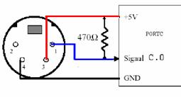
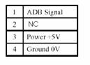
Figure 6. Touchpad connections.
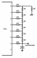
Figure 7. DAC connections.
Things we tried that didn’t work
(1)
Implementation
of PS/2
We initially tried to implement the PS/2 protocol (which is used by mouse on standard PCs) on the touchpad. The PS/2 protocol has a four pin interface, Vcc, Gnd, Data and Clock. This is a bidirectional asynchronous protocol which is completely governed by clock signals generated by the touchpad. The touchpad pulses the clock line 11 times for every byte which is transmitted or received; Start bit, eight bits of Data, Parity bit and Stop bit. The touchpad starts clocking as soon as Power is applied to it.
For the PS/2 protocol, we initially relied on the code that was implemented in a previous 2000 Final Project (Zen touchpad). This code is in assembly and is meant for a 8535 MCU. The various codes that we tried were:
(a) ‘C’ code on Mega32
(b) Assembly code on Mega32
(c) Assembly code on 8535
We consistently failed to get any results. L We hooked up the touchpad to an oscilloscope to detect the clock pulses but the device seemed completely dead. We also opened up a touchpad to verify the signal lines. After a lot of time and energy spent on this implementation, we decided to check the touchpad on a Mac computer and to out relief got a response. J
All this would have been avoided if we had been able to obtain any sort of documentation on the touchpad. But the touchpad came with no documentation and it was impossible to reach any support staff either. The data sheet we used is meant for “Synaptic” touchpads but it is generic enough for most purposes. We also completely relied on the “Zen Touchpad” project’s claim that the touchpad used PS/2 protocol.
Lesson learned: Make certain you have a datasheet. Make no assumptions!!!
(2)
Implementation
of Absolute Mode
The touchpad works in two data reporting modes:
(a) Relative mode
(b) Absolute mode
The default mode is the relative mode. We had originally planned on working in the absolute mode thus requiring us to modify the ADB register 2 which contains device specific information like version number, capability bits, mode byte, etc. The steps involved are
(i) Read Register 3 to verify the default relative device address of 3.
(ii) Verify Handler ID to be ‘01’, ‘02’ or ‘04’.
(iii) Verify device response to Talk 1 (Eight bytes with first four being ‘Synt’)
We obtained these steps from the Synaptics datasheet and implemented the same on our touchpad. Unfortunately, it yielded no results. We were unable to even read registers 1 and 2, both of which are defined to be device specific. The only explanation we can provide for this is that the touchpad we have is not absolutely Synaptic compatible. Fortunately registers 0 and 3 are more generic and having identical structure and accessibility for all kinds of touchpads.
Lesson learned: Get a device specific Data sheet!!!
The test codes for writing to a register as well as the PS/2 implementation code (Mega32 in assembly) are included in Appendix B. We are certain that given the correct touchpad (Synaptic compatible), the codes will work perfectly. Following the breakdown of the code, anyone can use these functions to retrieve data packets from the touchpad and write an algorithm that displays the data. The trickiest part was implementing the touchpad functions.