![]()
|
|
|
|
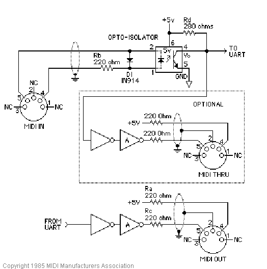
Hardware: Our first task was to turn MIDI signals generated by the Keyboard into something our Mega32 could understand. We found that the MIDI protocol was an asynchronous _______ which transmitted data at a 31250 BAUD rate. We found that if we passed the MIDI signal through an optoisolator (so the MIDI device and UART are not on the same ground) we read this signal with the UART on the Mega32. The optoisolator is used to make sure no weird ground loops are formed between the MIDI device and the microcontroller. These ground loops can cause 60 KHz noise to be mixed in with our signal and this is not desirable. The Optoisolator that our resources online suggested using was the HP6n138. We were able to successfully sample this part for free. We also had to splice a MIDI cable in half and determine which wires were we needed to plug into the optoisolator. Of the 5 pins used by the MIDI port, 3 of them did nothing. By trial and error, we found the correct two wires and were able to generate a signal coming out of our optoisolator.
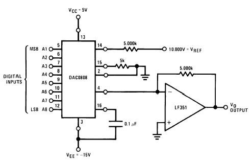
After the Mega32 has decoded the MIDI signal, the MCU produces an 8-bit sine wave onto PORTC. We use a 8-bit D/A converter to turn the digital signal into an analog voltage which can then be amplified and then played by a speaker. We used a DAC0808 as our D/A converter and a LF353 an our op-amp. We wired the hardware in this configuration.
The output of the DAC0808 is a small current value normally around 2 mA. The op-amp in this case is set up to amplify this small current and also turn it into a voltage level as well. The LF351 was chosen because it has a high slew rate (reacts quickly), requires a low input current, and has a large gain bandwidth. We used the LF353 which has two LF351's in the same package. The LF351 in this case is being used as a current-voltage amplifier. The voltage on Vo is fed into the TV speakers and then we have sound.
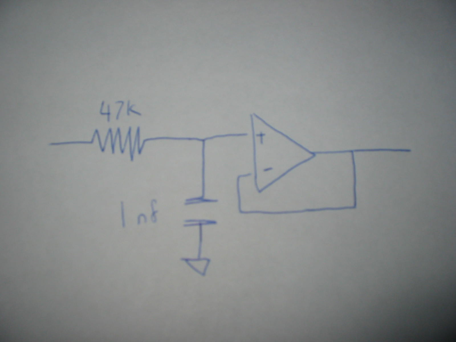
We found we were hearing noise from high level harmonics in the sine wave. To eliminate some of the noise in the signal we used a low pass filter. To find the correct value for our low pass filter, we had to find the time constant of the highest frequency we wanted to pass. The crossover frequency has a time constant equal to We didn't want values about 3.8Khz, so our value for RC was 4.17 x 10e-5. So we chose a 47K resistor and a 1nF capacitor. We also hooked the low pass filter to an op-amp configured as a follower. This creates a high impedance which we can use to drive the TV-speaker.
|
|
|