The hardware used to create our emulator was as follows:
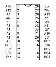
Creating the hardware interface between the Atmel microcontroller and the external memory chip was the heart of the hardware design. Since we were using a 32K memory chip, we were required to dedicate three of the Atmel's ports to this memory chip. Port C was selected to be the data bus between the memory chip and the microcontroller, while port A and port B were assigned to be a combination of the address bus and the control bits. The pin assignment for the memory chip is shown below:
Due to the fact that our design could only afford to use three ports to interface with the memory chip, we were forced to utilize only the lower 13 bits of the address bus, limiting us to the bottom 8K of the memory. The reason for this limitation was that the microcontroller needed to use 3 bits in order to communicate the three control signals: chip select (CS), write enable (WE), and output enable (OE). In the end, the combination of the 3 control signals, the 13 address bits and the 8 data bits completely used up three of the Atmel's ports (and the fourth port was already in use by the USART, described below).
A summary of the interface between the Atmel and the memory chip is shown in this diagram:
The fourth Atmel port, port D, was used to connect the Atmel to the USART. The lower two bits of the port were connected to the RS-232 send and receive bits. The following settings were used for the USART connection: a baud rate of 9600bps, 8 data bits, 1 stop bit, no parity, and no flow control. Additionally, since this RS-232 connection was also used to send the 6502 binary program data to the Atmel, we were required to set up a protocol for file transfer. We used the Xmodem protocol, which is described in the software section.