Hardware Design
The midi signal output by the music instrument is sent
through an optoisolator circuit to the UART of the
Mega32 microcontroller. The optoisolator
circuit keeps the music instrument and the sheet music generator system electrically
isolated from each other so that any current spikes present in the midi output
don’t affect the UART. Figure 3 shows
the hardware diagram.
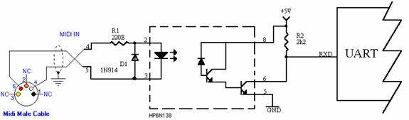
Figure 3:
TV Interface
The TV screen is painted by proper
voltage waveforms sent by the mcu through an RCA cable. We use a simple 2 bit DAC to convert the
outputs of pin 5 and 6 of PORTD to the proper voltage signals. The sync pulse corresponds to 0V voltage
level, black corresponds to .3V, and white is around 1V. The resistor values used in our DAC results
in:
|
Signal |
Pin 5 |
Pin 6 |
Voltage input to the TV |
|
sync |
0 |
0 |
0V |
|
black |
1 |
0 |
|
|
white |
1 |
1 |
|
where a value of 1 for the pin
corresponds to Vcc or 5V. When the
screen is painted, Pin 5 is set to 1 and Pin 6 is set to 0 if the pixel should
be black and 1 if the pixel should be white.
At the end of each screen line Pin 6 is set to 0 and Pin 5 is set to 0
in the ISR for sync-ing.
User and PC Interface
The user interacts with the sheet
music generator system using a keypad and through a GUI. The keypad is wired as shown in Appendix B. Key D enables transmission to the PC and key
# resets the sheet music.
*please see Appendix B for further
detail