Hardware
Hardware Used:
1 - Atmel AT90S8515 microcontroller chip
1 - Atmel STK-200 development board
1 - 32K external SRAM chip, 84256A-70L
1 – Octal D-Latch Chip, 74AHC573
1 – Digital-to-Analog Converter (DAC)
1 - 1k resistor
2 - 330 resistor
1 - 100 resistor
2 - diodes
1 - breadboard
2 - quad button pads
Our hardware design is almost identical to the hardware design specified in the
third course lab. The main difference between our design and the course lab design is
that we use a STK-200 development board with external RAM instead of a STK-500.
External RAM
The AT90S8515 has built-in support for external RAM access and usage in software is
enabled simply by setting a control register bit high. The STK-200 provides
transparent external RAM support, just place the RAM and latch chips in their sockets
and the required connections to the MCU are already in place. The purpose of the latch
chip is to enable bidirectional use of the A port so that only two ports and 2 pins
need be used up (16 bits for address, 8 bits for data, 2 bits for control). The
external RAM uses up ports A and C and 2 pins from port D (pins 6 and 7). This
unfortunately limits the number of available pins to us tremendously but it is
required for easy external memory access. We also took advantage of the fact that
PORTA[C] and DDRA[C] are unused I/O registers whose values are ignored by the memory
interface and are thus available for general use.
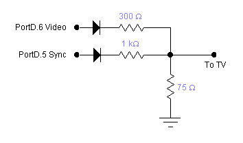
DAC
The DAC converts the digital signals from the microcontroller outputs and converts
them into analog signals appropriate for output to the TV's composite video input. The
basic DAC schematic is shown below and is identical to the ones used in labs 3 and 4.
The difference is that we are using PORTB.0 as the video output and PORTD.0 as the
sync output. Note that although only PORTB.0 is being used to output the video signal,
ALL of port B is used to hold the register being blasted. None of the other pins can
be used or else video speed will suffer.
Buttons
Two quad button pads were used to interface with the MCU. The buttons are arranged to
simulate the inverted-T arrow buttons fround on a keyboard plus one extra start
button. With only 5 pins available on the MCU, this is the best controller we could
implement. |