| ||||||||||||||||||||||||||||
| Variable Traffic Controller | ||||||||||||||||||||||||||||
Introduction | High Level Design | Hardware Program Design | Result | Conclusions | Appendix | References | ||||||||||||||||||||||||||||
|
Introduction | ||||||||||||||||||||||||||||
|
Our project is a Traffic Controller that is sensible to traffic condition and adjust the traffic
lights accordingly. Our project tries to simulate the traffic at an intersection, and with the use of sensors (Hall Effect in our case), we adjust the traffic of the intersection base on both the waiting time at the traffic light, as well as the rate at which cars passes the particular traffic light. We decided to have 3 levels of traffic condition, which leads to a total of 6 combinations of traffic conditions. Using these we are able to generate the appropriate timing for the traffic lights. The software consisted of three parts:
| ||||||||||||||||||||||||||||
|
High Level Design | ||||||||||||||||||||||||||||
|
Rationale: For most of everyone, whenever we go out to somewhere reasonably far, we'd probably drive a car (unless you don't have a car, and/or even a license like me (Raymond). As a driver, it's almost certain that every time you drive, you are going to hit something: not a person, not a car, not a lamp pole or anything of that sort (hopefully), but you sure going to "hit" a traffic light. Since it's almost impossible to live without a car nowadays, traffic jam is always a big pain whether it's the city or not; so we came up with the idea, designing a smart traffic control system. Logical Structure: The components are separated very clearly. The traffic controller runs with certain preset values, and after it begins it will adjust the traffic base on the input from either the pedestrian(s) or one or more of the four sensors. These input will lead to one of the 6 different conditions, and the traffic lights are adjusted accordingly. Hardware/Software Tradeoffs: The project utilizes both software and hardware to accomplish its goal. To detect the traffic we need to use both the traffic sensors and the programmed development board to read and process the sensor input, it's important as we could not have done this without either one of them. The similar technique applies to the pedestrian inputs as well, with the exception that simple logic unit is added to save I/O ports. The traffic controller itself, on the other hand, is mostly done by the software controller in the programmed chip, it'd be very complicated to do this with pure hardware, and software is therefore the choice to go. | ||||||||||||||||||||||||||||
|
Hardware/Program Design | ||||||||||||||||||||||||||||
|
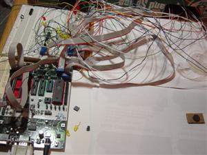
Program Details: The most important and tricky part of the code is the traffic sensor. We have to detect a different sensor input from each direction. At the same time, the opposite directions on the same road are somewhat related to each other. Thus it's very hard to determine what goes on when the two directions traffic are combined, and it's tricky in terms of how to do the math and determine the traffic condition. In our design we separate all the asynchronous inputs from the normal, or regualar, traffic light system. The two pieces are just add-on to the regular system and thus doesn't change it functionality by much. The first part is the pedestrian inputs, we utilize the push buttons on the STK 500 board and then feed these button input to an AND gate (originally we would be using 4-inputs AND with 4 pedestrian inputs on each road, due to time limitation we are only using 2-inputs AND with 2 pedestrian inputs instead) and its output is connected to the input pin of the appropriate PORT. As a result of that we are only using 1 pin for all of the pedestrian inputs, whether it's 4 or 2 pedestrian inputs, we can use 1 pin to detect that as either one of them will activate the same routine of modifying the traffic light. On the other hand, since each sensor activates their own routine, they each need a specific pin to feed the input, we only use 2 per road, thus there's only 2 inputs per road, making a total of 4 inputs, but it is very possible that there's more sensor inputs in diffrerent designs. After detecting the wait time and rate of traffic, the system adjust the traffic base on these values, and update the system status, there's six different presets to select from, and the system is updated every "cycle", which is the time it takes for the traffic lights to go back to the same state it was from. Hardware Details:  Initially, we tried the Hall Effect sensor by connecting Vcc pin to power, Gnd pin to ground, and
output pin directly to the port of the micro. The result is that when the sensor is off, the output
voltage is zero; when the sensor is on, the output voltage is less than 0.1. This makes it difficult
for us to use the sensor because it is logic '0' when it is both on and off.
Initially, we tried the Hall Effect sensor by connecting Vcc pin to power, Gnd pin to ground, and
output pin directly to the port of the micro. The result is that when the sensor is off, the output
voltage is zero; when the sensor is on, the output voltage is less than 0.1. This makes it difficult
for us to use the sensor because it is logic '0' when it is both on and off.To solve this problem, we first consider a voltage amplifier that will amplify the voltage high enough to be seen as logic '1' when the sensor is on. However, it is difficult for us to determine how much the voltage should be amplified so that it is reliably above the switching voltage of around 3V.  We tried to look for an alternative solution that is easier to carry out. We thought that voltage divider
would be a solution so we constructed a voltage divider as follows.
We tried to look for an alternative solution that is easier to carry out. We thought that voltage divider
would be a solution so we constructed a voltage divider as follows.The result is that when the sensor is on, the voltage at X is very small (logic '0'); when the sensor is off, the voltage at X is 5V (logic '1'). These voltages are good for microcontroller inputs. Our problem of reading the values from sensor was solved. To organize the structure of our design as well as minimizing the resource required, we limited ourselves in using exactly 1 I/O port for each set of traffic light (in direction). The pins assignment are shown below:
Code/Design Reference: We did all of the design work from scratch, although we are aware of the probability that resources are out there with similar design, but since we have the scheme already planned out, we decided to conduct no research during the design process and to do everything from scratch Difficulties: Our original design was to use distance sensors to test the existence of cars. The first choice of our design are ultrasonic distance sensors sold by Jameco (Part # 136653 and 139491), but since we needed a minimal of 4 sensors to have a realistic detection of traffic and they each cost $6.95, we decided to go look for other parts. We then come to think of using the IR sensor, the second best choice as it only requires an object to be close enough to activate the sensor output. However our order was never shipped, despite we ordered it during the first ordering, this leave us in a very bad situation because our original design is meant for this type of sensors. With some luck we are able to get the Hall effect switches, they are cheap and quite reliable. We ordered the parts from All Electronics Corp, the order however arrived late again (but at least it was shipped), which stall us quite a bit as we don't know how would we be using it until we get them, and also it took us a good amount of time to modify our code design to meet with the new sensors. Fortunately it turns out to be quite reliable and we are able to device a way to use it without having problem. | ||||||||||||||||||||||||||||
|
Result | ||||||||||||||||||||||||||||
|
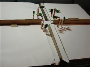
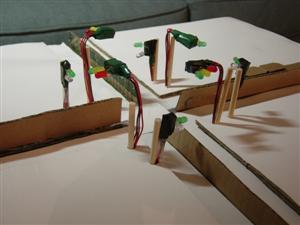
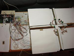
Testing Results: There were problems when we tried to solder the wires, the wires are not too flexible and that leads to many broken wires at the connecting point. We discovered a solution by first locking the wires by twisting them, and we put soldering iron on top of it afterwards. This works much better and we do not have the broken wires problem after fixing these broken wires. They are very disturbing because we can't tell when a wire is broken (connecting points are all covered with electrical tape) by looking at it. After this we had problem for a time programming the chip, this was due to fact that we are using PORTB in our code. Since PORTB is the programming port, if we are using it in our code it might be unable to drive the port and program the chip as it is supposed to. We fix this by unplugging the PORTB from the ribbon cable from the controller board, then program the chip, and reconnect the ribbon cable back to PORTB. For a time we also had problem with the sensors positions as they kept moving due to the weight and the movement of the wires. If the sensors are out of place then the sensors won't work, and constant movements can also cause the wires solderings to break. Our solution is to use cardboard to afix their position at the soldering point and use powerful double sided tape to avoid both sensor and wire movements on the model. As a result of that the problem with the sensors positions is fixed. After getting through these various problem, we are able to begin our testing, there are total of six different combinations:
We tested out each configuration by creating different traffic conditions on our own using the magnetic cars, the result is quite resonable and we are quite satisfied with the testing results. We repeat the testing several times to ensure validate the correctness of the algorithm. We also tested the pedestrian inputs quite extensively, it's able to ignore the inputs if the traffic is HI, and otherwise adjust the traffic according with a limit on how often one can reduce the waiting time, thus pedestrians may not just keep pressing the button and cross the street quickly. Speed of Execution: There's no problem within this category as the "cycle" is in the order of more than one minute. Accuracy: There's not enough time for exhaustive testing on the design due to the limited timing after the IR sensors are confirmed to be not shipped. For cases in which we are able to test we were able to get reasonable results from it. Safety: There should be no safety issues involved in this design since there's no high power mechanical parts or laser beam within the system. Interference with Other People's Designs: We did not encounter any problem of this type in our design, and it's believed that we are safe from this type of problem. Usability: It is actually possible to use it in a real life situation given the relative separateness of the traffic control from all other parts, with the add on of the variable traffic control the system should still be correct and that it will not be causing accident due to bugs in the coding or design of the system. In fact, in order to prove its true correctness and efficiency, one must apply the system in a real life situation and see how the algorithm reacts to the environment. | ||||||||||||||||||||||||||||
|
Conclusions | ||||||||||||||||||||||||||||
|
Analysis: After testing and simulation, the results met our expectations very well. When we simulate low traffic, we move the cars occasionally on the road. When we simulate medium traffic, we move the cars more frequently and make a car queue on the road a while after the light turns red. When we simulate heavy traffic, we move the cars at high frequency and make a car queue right after the light turns red. These traffic situations simulate the real-world traffic fairly well. If we were to do the project next time, we would include more different cases that distinguish different traffic situations. Currently, our traffic detection algorithm relies on detecting the number of cars passed by, and if there are long car queues. In order to distinguish more traffic conditions, we need more sensors and probably different kinds of sensors, along with more sophisticated algorithm. In our design plan, we planned to use IR sensors as well. However, the parts did not arrive so that we had to finish the project with an alternative, Hall Effect sensor. Next time, we could use the IR sensors instead of the Hall Effect sensors so that the model is more realistic. We would also try distance sensors so that we can effectively detect how long the car queues are. We would adjust the timing of the traffic lights differently. Currently, we detect the traffic condition and set the traffic lights with fixed time intervals. For example, if the traffic is heavy, the duration of green light will be 60 seconds. Next time, we could adjust the time intervals relatively. For example, the duration of the green light can be even longer if 60 seconds is found to be insufficient. Also, we would expand the model by adding more lanes. In addition, we would implement more functionality such as the left-turn signal and detect cars that run the red light. Intellectual Property Considerations:
We found that our design project is related to the following points in the Code of Ethics:
We are honest with the testing results. The results are realistic that the side with more traffic will have more time for green lights. The timing of the traffic lights is heuristic and there is some estimation involved. Our project intends to explore the improvement of the traffic conditions with sensors in application. This project uses sensors to detect traffic and then control the traffic lights accordingly. Our model can build up incrementally by using other sensors, adding more intersections, and more sophisticated algorithms. When we are building the model, we thought about how to make the traffic lights. We seek for advices of how to model an intersection. We got inputs from the professor and other people. The criticisms include: the model should be realistic and look like a real-world intersection, and the placement of the sensors. During the project, we assist each other in our professional development by learning from each other. Often there is something that one partner knows and the other does not. We also support each other in following this code of ethics. | ||||||||||||||||||||||||||||
|
Appendix | ||||||||||||||||||||||||||||
|
Code Listing: Due to the long length of the code listing, it's not included as part of the webpage, you may view/download one of the three format using the following links: (html|pdf|c) Schematics:    Cost Details:
|
||||||||||||||||||||||||||||
|
References | ||||||||||||||||||||||||||||
|