 by David Tow and Emily Cheng
by David Tow and Emily Cheng
The hardware design for this project is slightly tricky. The hardest and most time-consuming part of this design was getting all the hardware parts to communicate properly with each other. Constructing the keypad side microcontroller design, an off-board microcontroller, was interesting.
We followed the diagram given on the Build your AVR Starter Kit page. We place one 27pF capacitor to pin 12 (XTAL2) and one to pin 13 (XTAL1) with a 8MHz crystal between those two pins. We place a 160 ohm resistor at pin 9 (reset') to pull the reset' to high to prevent constant resetting. Usually, reset' does not require a pullup, but with the RF transmissions, there is added RF distortion on the chip, which requires the pullup at reset'. After many tries with different resistor values, we found that a 160 Ohm resistor gave the best result at pulling up reset'. This does cause a decent amount of current to be sucked from the battery source, but when we tried using a 10k Ohm resistor, there was still constant reseting. To program the chip Pins 6 to 11 are connected to SPROG3. Between Vcc and Gnd, there is a 0.1uF capacitor.
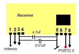
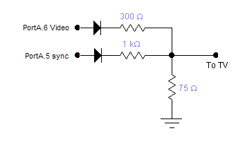
On the TV side, there were a few connections needed between the TV MCU and the TV-side hardware. Here are the port/pin connections for the TV side:
PORT D PORTD.0 to Receive data pin PORT A for TV Images PORTA.6 to video PORTA.5 to sync NOTE: We place an operational amplifier
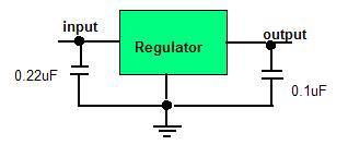
between the receiver data pin and PORTD.0 to amplify the received signal. We amplified the signal from 3.8V to 4.6V. On the keypad side, there is more hardware used. We use four AA batteries as our power supply for the keypad off-board MCU. We also use a voltage regulator to keep the voltage constant at 5V.
The connection of the regulator to the board is shown in the diagram below.
The input pin is connected to the positive side off the battery and the output pin is the 5V power supply of the board. The keypad port/pin connections are listed below: PORTB.1 to button 2 PORTB.2 to button 3 Keypad and TV are connected as used in labs 5 and 3, respectively.
Transmitter and receiver connections to their respective MCU's are shown below:
PORT B
PORTB.0 to
button 1
PORT C
to Keypad
PORT D
PORTD.1 to
transmitter data pin
![]()