Schematics
Figure of the mouse sensor circuitry, where the output is high when nothing obscures the photo emitter to the sensor and low when the sensor and emitter are blocked.
Figure of the light/photo reflective sensor QRB1114 as used to determine light and darkness of the image.
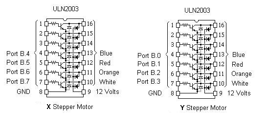
Motor hardware setup used to drive the motors.
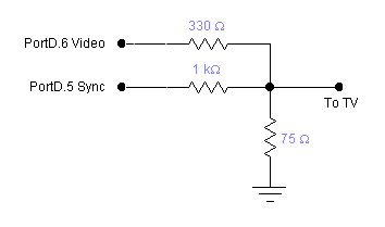
Figure of the schematic for the TV circuit courtesy Bruce Land