ECE 476: Microcontroller Design
Final Project: Digital Compass

|
| Image Courtesy: Carbon Buster Inc. |
Introduction | High Level Design |
Program/Hardware Design | Results |
Conclusions
Appendix | Acknowledgements |
References
The goal of this project is to build a digital compass that displays both the direction and cardinal points on a
television. Other functionalities were added to complement the sensor interface, such as, temperature display,
magnetic declination input and disability option.
At the highest level, this project involves acquiring two output readings from the Hall-effect sensor (Dinsmore R1655)
and processing the data through the ADC and output the directional information onto a TV screen. The first part involves
amplifying the two output voltages and feeding them into the Mega 32 ADC input. After that, extensive calibration was
necessary to accurately decode the input voltages into useful directional information. A mapping was done to the
flash memory to retrieve the direction accordingly to different sets of inputs. As a matter of fact each pair of inputs
were unique, so mapping them made sense as timing is an issue when using the TV as an interface. Finally disability option
was added to bip at different frequencies depending on the desired direction entered by the user. Additionally adding a
magnetic declination feature enables the compass to display the true north rather than the magnetic north as a function of
current location.
[back to top]
1. Idea and Motivation
Our motivation originated while surfing through Amazon.com and checking the Electronics Section. We came upon a cool
digital compass but the price wasn't. Upon that day we decided to
replicate it by using a sensor and integrating into Mega 32. Ideally we wanted to display on a graphical LCD but due to
the budget constraint we restrained ourselves by using the TV provided in the lab.
2. Design Overview
The core of our project centers around the hall-effect sensor. Basically the sensor outputs a sine-cosine curve pair
which may be interpreted by Mega 32 into directional information. The sensor requires a regulated 5 V DC input, hence
we used the voltage supplied by the STK 500 board. The first trick involves reading one channel at a time in ADC. This
was accomplished by toggling the channel each time a data is read. After that calibration of the compass was done, this part
involved recording the ADC value every 10 degrees. A simple interpolation scheme was performed on the acquired data in
Matlab.
The interpolated values were then exported into the flash memory and mapped accordingly to the input channels. Each input
channel would retrieve two possible degrees from memory since we are dealing with sine-cosine functions. These four values
(two for each channel) are then compared using a simple algorithm and the correct degree information was passed onto the
screen using schemes learned in Lab 4. After some debugging and verifying the accuracy of the displayed value, we went on
to display the circular plot with the eight cardinal points plus a directional pointer.
After we successfully got the sensor to work with the display, we decided to incorporate additional features that would
improve the user interface and the practicality of the digital compass as a standalone application. First we added a
disability option. This feature enables a person with visual disability to interface with the digital compass. The user
can enter a desired direction (N,E,S or W) and the digital compass would bip according to the proximity of the current
direction to the desired direction. The bip sound was designed to be as a function of both frequency and pitch, that is,
the higher the frequency and pitch the closer you are to the desired direction.
Lastly, we added a magnetic declination option in order for the digital compass to display the true north. This feature is
initialized to 11 degrees West (Ithaca, NY) and the user is allowed to adjust by pushing two of the buttons on the STK 500.
Adjustments to the previous readings were made accordingly to display the direction correctly.
3. Hardware/Sofware Tradeoffs
The use of TV in place of a graphical LCD proved to be viable, but with limited capability and user interface. The main
advantage comes from the fact that the TV was used in Lab 4, hence some of the code could be re-used and the knowledge
and experience proved to be invaluable.
In terms of software, we decided to re-use some of the codes provided by Professor Land and code entirely in C rather than
assembly. This limited the functionality of our design due to time constraint, but at the same time it eased the complexity
of our project.
4. Standards
The main standard used in the project is the RS170 composite video standard and the NTSC frame rate.
Our video signal is non-interlaced, black and white video. The standard requires 3 voltage levels to generate sync, black
and white signals along with horizontal and vertical sync pulses. All drawings must be carried out during TV scan line 230-260 and 1-30
to avoid visual artifacts.
5. Patents and IP
Robert C. Dinsmore holds a patent for portable electronic compass. His invention comprises battery operated compass
utilizing Hall effect digital switches to sense the orientation of the compass in relation to the earth's magnetic field.
Decoding of sensor output were used for alphanumeric display.
Though our digital compass has similar feature found in Dinsmore's invention, we believe our approach and design are
completly different. However, we credit the usage of his intellectual property as the basis of our project. Additionally
we need to credit Professor Land for supplying the core code for the TV display in Mega 32. We used his code as the
starting point for our project.
[back to top]
1. Program Details
The core of our program was derived from Professor Land's demo code provided in Lab 4. The first modification was to enable
the ADC to read three channels. A simple state machine with switch statement was used that basically changes the ADMUX
channel selection after it reads a channel input. For example, when channel 0 is read, we change the ADMUX channel to 1, so
that the next time around the switch statement enters to channel 1 case and reads its value.
After verifying the functionality of the ADC reading, we calibrated the analog sensor by taking a reading every 10 degrees.
Figure 2 below depicts the two output curves obtained from the ADC:
 |
| Figure 2 Sensor ADC output |
Next part involved using the data collected above and interpolating the values between each reading. This was accomplished
by using Matlab. The result was then put into flash memory for easy access. An algorithm was required to compare the four
directional values from the memory and picking the right value to display on the TV. This proved to be tricky since
the interpolatd value were not ideal and manipulation on the data was necessary. To put it simple we took the difference
among all four values and used this information to pick the correct direction to display. More details can be found
in the code.
 |
| Figure 3 Digital Compass |
The circular plot and the directional pointer was first done in Matlab and then transferred into C program. For the pointer, we
basically needed an end-point since the starting point is always fixed in the center of the circle. So in Matlab we simulated
such situation, which would give us all the end points required for a line to be drawn from the center.
These end-points were also stored in the flash memory to provide easy access from the main loop. A picture of
the simulated circle plus the direction pointer is shown in Figure 3 above. A demo movie of the digital compass been
operated can be seen here.
Adding sound into the digital compass provided a nice feature to the system. We used the TCCR0 and OCR0 to
produce the bip sound. Frequency and pitch were adjusted accordingly to reflect the current position with respect to
the desired location. We also added a feature that blinks in the direction that the user wants to go. Also under
this mode of operation the circle has four cardinal points around it as shown in Figure 4 below.
Here is a link that demos the compass operating with the desired direction set to North.
 |
| Figure 4 Alert mode operation |
The magnetic declination involves detecting the push button on PORT C and adjusting the output reading found above according
to the amount of declination. This part is a little tricky since our design involves mostly mapping. The main issue comes
in finding end-points stored in memory for the directional pointer. This can be solved by correctly adjusting the value if
it is either positive or negative. Here is a link of magnetic declination been adjusted by a user.
Lastly, the temperature sensor was added into the system. This proved to be the easiest task since we dealt with this
component in Lab 5 and integrating into the digital compass was easy.
2. Hardware Details
This part may seem to be trivial initially because most parts were used previously in our labs, except the compass sensor. The
sensor required a lot of work to get it to work reliably. At first we hooked up the sensor onto the breadboard, and
added some gain to both output signals in order to make use of the full range of the ADC converter. Low-pass filter was
also necessary to filter out some of the noise present in the signal. Calibration was done as mentioned above. This method
proved to be inaccurate since the sensor was very sensitive to even slight displacement on the breadboard.
A new method was used to hook up the sensor onto the breadboard. This involved drilling tiny hole into a plastic cap and
mounting the sensor onto it, as shown in Figure 5 below.
 |
| Figure 5 Wiring Detail under the Cap |
This plastic cap provided the necessary stability for the sensor to remain fixed under certain
displacement. The idea proved to be sucessfull at the end and a more reliable compass reading was possible.
Other hardware components involved temperature sensor, amplifier, filter, Video DAC all shown in Figure 6 below.
 |
| Figure 6 Hardware Components |
Below is the button configuration on the STK 500 used to enter different modes of the digital compass:
 |
| Figure 7 STK 500 button configuration |
A TV is used for diplay. The current temperature, direction (in degrees from North), approximate cardinal point,
and the chosen magnetic declination (default to be 11 degree to the west) are displayed. An emulation that imitates
a conventional analog compass is placed in the center of the screen. Figure 8 below depicts how the information is
displayed on the TV screen.
 |
| Figure 8 TV Screen Display |
3. Things We Tried That Didn't Work
Other type of sensors were used and tested (also from Dinsmore). The 1525 proved to be not as accurate as R1655, since
its output swing was lower hence less dynamic range for the display. The digital sensor was also tested but it proved to
be innacurate.
[back to top]
1. Speed of Execution
The main delay comes from the sensor itself. A finite delay is expected for the sensor to adjust to a given position,
though such delay is almost negligible. Also, one channel is sampled every frame, so there is certain latency involved in updating
the value from the sensor output. Again, from a human perception this is not noticeable.
2. Accuracy
The accuracy of this design involves primarily in the value of degrees displayed on the TV. To our best knowledge, the
compass is accurate to at least 5 degrees, though for most portion the accuracy is up to 2 degrees. There are some
instances where the sensor output is inaccurate, hence the value is reflected on the output. So, in some sense our level of
accuracy is limited by the sensor itself. For most part and considering the price of the sensor we believe a good level
of accuracy was achieved for this design.
3. Safety
This design is completely safe to any human interaction. This is due to the usage of low voltage and currents in our
circuits. Also the digital compass involves no human interaction, other than push buttons in STK 500. Though the sensor
is sensitive to external field and magnetic, we found the interference has negligible effect in our operation.
4. Usability
The digital compass is a portable device to be easily carried around in a pocket. Unfortunately, for our device the TV
was chosen as the display. This would be impractical in real life, since carrying a TV around with you would be hard
to move around. As for the user interface, we believe the two modes of operation allows the user to easily locate himself
without worrying too much what is shown on the display. This extra feature allows the user to set a course and move
around. Additionally, this device allows people with visual disability to walk around without worrying whether they will
get lost or not. Plus, the magnetic declination allows the digital compass to be used anywhere in the world, a simple
adjustment in the reading allows the user to locate the true north.
[back to top]
1. Analysis
Looking back at our proposal, we believe our goal was accomplished successfully. The accuracy of the digital compass
is better than we expected. Obviously we see further improvements can be made in our design. Firstly, we would want
to use a graphical LCD which would allow an easier integration with the MCU since a protoboard could be used and
carried around with the LCD. This would allow better comparison with commercial digital compasses and demo would be
much more fun. Secondly, it would be nice to have some GPS system to automatically track the current location and
adjust the magnetic declination automatically. Lastly, we would like to have some form of auto-calibration so that
the digital compass can be calibrated every time it starts.
2. Standards & Intellectual Property
Again, we acknowledge the use of Professor Land's video code as the starting point of our project. Other than that,
the code used in this project is entirely our design. We do not feel any patent opportunity to be available for this
design since commercial ones are more practical and easy to carry around. Also, we would like to recognize the patent
give to Robert Dinsmore, though our design is entirely different.
3. Ethical Considerations
The IEEE code of Ethics was obeyed in this design from start to end:
1. to accept responsibility in making engineering decisions consistent with the safety, health and welfare of the public,
and to disclose promptly factors that might endanger the public or the environment:
We made sure our design was safe for people to interact with. This was our main concern since a digital compass is supposed
to allow a user to carry around without any safety concern. Additionally, we kept the graphical interface on the TV simple
so to avoid timing issue that might have caused flickering and eye strain.
2. to be honest and realistic in stating claims or estimates based on available data:
From the very start we set a goal that was viable in our perception. This enabled us to focus on the goal and striving for
it. Hence the claims stated in this design matched well with our vision so honesty of our final result cannot be
contested.
3. to reject bribery in all its forms:
Once we were done integrating the digital compass with the MCU, we could have demo and gained more points. But, we
decided to add more features to complement the digital compass. This made our design much more fulfilling and a sense
of a great accomplishment could be felt.
4. to maintain and improve our technical competence and to undertake technological tasks for
others only if qualified by training or experience, or after full disclosure of pertinent limitations:
The use of the Hall-effect analog sensor with the MCU have ensured a better understanding of how the sensor works and
how a digital compass can be built with the help of a microcontroller. Indeed, the design process has helped us have a
better understanding of the NTSC standard, sensor and Mega 32.
5. to seek, accept, and offer honest criticism of technical work, to acknowledge and correct errors,
and to credit properly the contributions of others:
We have acknowledged the contribution of every person that have made this project possible. This is an important
fact to be stated and should be put in practice every time one writes up about their design.
[back to top]
1. Schematics
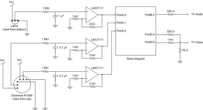 |
| Figure 9 Top Level view of the schematics used in this project |
2. C Program
3. Cost
Our project was completed within the $40 budget constraint. Here are the costs:
| Parts |
Cost |
| Mega 32 MCU |
$8 |
| Sensor (R1655) |
$18.50 |
| 2 Breadboards |
$10 |
| TV |
Free |
| Op-amp (LMC7111) |
Free |
| Temp. Sensor (LM34) |
Free |
| Resistors and Capacitors |
Free |


