Home Security System
A Cornell University ECE
476 Final Project
by
Chun-Pai Jimmy Hsieh &
Yang Cao
This is a digital home security system with voice feature
which can monitor room temperature, smoke, motion, and windows & doors.
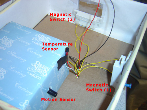
The goal of this project is to utilize the after-market parts and build an
integrated home security system. Besides traditional magnetic switch equipped on
doors and windows, we have also incorporated temperature sensor, smoke
detectors, and motion sensor. Hence the security system will sound an alert when
there is an attempt of break-in or if there is possible smoke or fire.
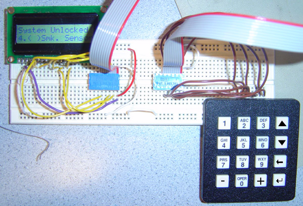
The system is fully digital and also be fully customized. It incorporated a 16x2
LCD display with a 4x4 keypad. Each sensor can be enabled or disabled, and alarm
frequency and skim can also be chosen by users. We have also equipped a voice
playback chip, and it will speak which sensor has gone wrong.
High Level Design
Project Idea
The idea of our project comes from lab 3 when we did a simple security system. However, that security system is quite basic and only offers simple password lock. Hence we would like to enhance our security system with different kinds of sensors. We have also browse some of the old final project and found the "Phone Dialer" project from spring 2002. Originally, we were going to put Zarlink MT8880C DTMF transceiver chip, so it will dial a desire number that user specify. When the phone connected, we will use Winbond ISD1420 voice record and playback chip to play pre-recorded voice signal. However, due to the lack of the phone jack in the lab, plus the majority of the Cornell campus has digital phone line instead of analog phone line, we decided to put away this idea. Since ISD1420 chip has address bit feature, we decided to make our system playback certain pattern of voice when the system goes into alert status.
Logical Structure
The logical structure of our design is shown in the block diagram on the right. The central system will handle all the sensors and keypad input, output information to LCD screen, indicate system status on LED, and make buzz or voice alarm.
Hardware & Software Tradeoffs
The IR motion sensor is quite inexpensive ($5.99 dollars for the one we got), so we also decided to buy it instead of building one on our own. We also acquire one of the smoke detector from home. This is the very basic version and will sound the alarm when the smoke is detected.
Besides some necessary capacitor and resistor connections to the ISD1420 chip, the majority of our project is based on our software. This is mainly because our system if fully customizable and has quite a lot of features. It need to monitors all the sensor, and time the appropriate seconds in order to play certain voice pattern (ex. "Temperature, smoke error, please…" "Door or window error, please…") depending on which sensor goes wrong. It also need to handle the user interface via keypad and LCD screen. All of these are programmed in our software.
Standards
The 16x2 LCD we use has standard 16 pin connection (pin 15 and 16 for LED backlit power). The keypad is also standard 4x4 which has 8 pin connector. The smoke detector is powered by standard E-block 9V battery. The motion sensor is powered by 2 AAA 1.5V battery in serial.
Existing Patents, Copyrights and Trademarks
The magnetic contact switch is manufactured by SECO-LARM? The motion detector is manufactured by SPY GEAR. The smoke sensor is a little bit hard to identify because we do not have the original box, but we believe it manufactured by FAMILY GARD?
Program Detail
The hardest part of the program is timing. When any sensor goes wrong, the program will wait for certain seconds (set by user), and then make ISD1420 chip play back the desired voice pattern we want. Originally, we though we can just output the appropriate address bit and then make the chip play, however, later on we discovered there is a THOLD in the ISD1420 chip that we need to take care of, otherwise it will reference to the previous address bits. The voice playback chip does not have a very fast internal clock, so we have to manually use the delay function in our program after we set the address bits, and then make the chip play. Although using the delay function is somehow undesirable, however, we have implemented our program such that this delay will not cause any error in our software.
Besides, we also need to implement the keypad function so it acts accordingly when the LCD is displaying certain menu. This is not very difficult but we have to take care of all the possible circumstances. We have 12 submenus in our system. Set temp define the lowest temperature allowed before sounding the alarm (70~120F, with step size of 1F). The Sec. Allow is the time in second before the voice alarm goes off (0~30sec, with step size of 2 seconds).
1.Enable System
2.(*)Temp Sensor
3.(*)Mot. Sensor
4.(*)Smk. Sensor
5.(*)Mag. Switch
6.Set Temp: 100F7.(*)Voice Alarm
8.(*)Buzz Alarm
9.New Pswd:
A.Buzz Freq: 7
B.Buzz Skim: 3
C.Sec. Allow: 10We also have simple de-bounce feature for our keypad, and it will sound a buzz when you press any key (if you HOLD a key but buzz will only sound once). Although the de-bounce function is as easy as few lines, it takes a while to think about the logic and how to actually implement it. Also we implement the backspace feature so that when use enter a wrong password, this key can be used to delete the previous entered number. Also just a quick note, our password is masked on LCD for a safer purpose.
Hardware Detail
The first sensor we have is the temperature sensor. Since we implemented a digital thermometer in lab 5, we decided to use the same circuit. So we incorporated National Semiconductor LM34 temperature sensor, with National Semiconductor LMC7111 OpAmp chip to amplifier our output voltage going into ADC. The final connection of our circuit look like the following.
The second sensor we have is the motion sensor. Although we do not have the diagram of the circuit (it has some IC components), we discovered there are few NPN transistors in the circuit. NPN transistors are like switches, so it is obvious these are used enable the original buzzer on the circuit. Hence we took the base pin together with ground to connect to our ADC pin input. If the voltage exceed VTH (threshold voltage), we know the alarm goes off.
The third sensor we have is the smoke detector. The smoke detectors mostly equipped with piezoelectric buzzer, which has F (feed back), C (main electrode), M (metal plate) three pins. Piezoelectric buzzer has an internal crystal and will sound if small current is applied (voltage drop). Hence we took out the piezoelectric buzzer and connect the F pin into our ADC input. When the sensor goes off, the voltage will go high.
The final sensor we have is the magnetic switches. It is normally closed. So when the switch is right next to each other, the resistance is zero. When the switch is separated, the resistance will become infinity as if it’s disconnected. So we drive the switch with an 10K pull-up resistor, and connect the output to the ADC. Since we have two magnetic switches, we decided to build a simple AND/OR gate by using 1 74LS00 chip. There are four NAND gates in 74LS00, and if we connect two of NAND gate in parallel with their input signal to another NAND gate, we will get as if there are 2 AND gate in parallel with their signals to an OR gate. The diagram can be found in our appendix.
The 4x4 keypad has the layout like the table on the right. The - and + buttons next to 0 can increase numbers in the submenu, such as time or frequency. the UP and DOWN button next to 3 and 6 will navigate the menu. BK is backspace while entering the password. EN is enter and is used do enable/disable menu item or enable the system.
1 2 3 ˆ 4 5 6 ˇ 7 8 9 BK - 0 + EN
Reference Design
The Winbond ISD1420 voice record and playback chip also requires external resistors and capacitors. We build the circuit from the reference circuit on ISD1420 specification sheet. The modification we have is to connect the address bit to our PORTB on our MCP, and PLAYL to our pin 6 in PORTA of our MCP. The specification of this chip can be downloaded from the appendix. In addition, we also learn some information about piezoelectric buzzer from this website http://www.imagineeringezine.com/e-zine/beeper.html.
Speed of Execution
The speed of the execution is work very well. In the beginning the system will boot up with default password 1234. The user can now navigate through our menu, and enable or disable each type of sensor. If a particular sensor is enabled, the LCD screen will output a * symbol before the sensor name. User can also set the alert temperature, enable/disable voice or buzzer alarm, and even specify the ring tone and frequency of the buzzer alarm and the time before voice alarm goes off. The button de-bounce scheme also works fine so users can navigate through the menu and use the keypad perfectly.
Accuracy
After the user enables the security system, the green status LED will lid to indicate the system status. User can now enter proper password to unlock the system. If any sensor goes wrong, the LCD will output ERROR and with proper initial for the sensor (T for temperature, M for motion, S for smoke, D for door or window magnetic switch). The red led light be will flashing at 4Hz to indicate such event. If the buzz alarm is enable, it will sound the tone that user choose. If the voice alarm is enabled, it will wait for few seconds (user specified), if the system is still not locked, then it will start playing voice to indicate which sensor goes wrong. (For example, "Temperature Error, please check and unlock the security system.") If another sensor goes wrong after that, the system will also act accordingly and indicate that in the voice alert in addition to the LCD screen. ("Temperature Motion Error, please check and unlock the security system.")
Safety
As soon as user enters the correct password, the system will be unlocked and the buzzer and voice playback will stop. The user can now navigate through our menu and make any changes in the settings.
There are two kinds of smoke detectors, ionization chamber and photoelectric smoke detectors. Ionization chamber one is more popular due to its low cost. Our smoke detector from home also has an ionization chamber. However, this kind of smoke detector has a small amount of radioactive material (americium-241), which has a half-life of 432 years (alpha decay). We have checked the specification of such radioactive element and government web pages regarding to such kind of material. We have found such radiation is relatively small as long as we do not inhale or swallow it. The exposures is relatively weak so as long as we are not in touch of it all the time, it is relatively safe to operate the smoke detector.
http://www.epa.gov/radiation/sources/smoke_alarm.htm
Usability
Our home security system is very practical. It can be used not only in the home environment but also in a business environment too. It can monitor the surrounds to not only protect our properties but also our lives. Besides, it can be highly customized to suit each one's need and preference. So our security system is very useful for us as well as other people. We believe every house in the world should equipt a security system like the one we design.
Expectation and Improvement
The result of our design has met our expectation, in which every sensor is working and will sound specific alarm when the system goes into alert status. The keypad and LCD also offer great interface and users can be familiar with our system in less than few seconds.
If we have chance to design this project again, we will add a phone dialer chip like the Zarlink MT8880C we mentioned before. By doing so, we can make sure if no one is at home or if no one is around the area, someone else can be notified to take immediate action. In addition, we feel like our PORTB is a little bit wasted. We only have 4 output patterns but we are using all 8 pins. Next time we will use 74LS series chip together with only 2 output pins from MCP, so together we can save 6 I/O pins. Besides, we will like to have another small microcontroller at a higher frequency, so we can output our buzz alarm at a higher frequency tone.
Intellectual Property
Besides the reference circuit from ISD1420 chip specification, reference keypad decode scheme from lab 3, and temperature sensor circuit from lab 5, we have designed and coded everything on our own. There is no code from public domain, and we did not reuse any code from the previous lab (we do reference, but not copy). Because we are using two pre-built sensor circuits (motion and smoke sensor), we feel like we should not pattern our whole design. However, if we take out these two parts and only have these “inputs,” we definitely have opportunity to pattern our design.
Ethical Considerations
Reference to IEEE Code of Ethics, we have try our best effort to meet all requirements. Here are the few examples.
1. To accept responsibility in making engineering decisions consistent with the safety, health and welfare of the public, and to disclose promptly factors that might endanger the public or the environment.
Our design kept safety as one of the top priorities. For example, we could have built the smoke detector circuit on our own. However after we found out that it’s radioactive and it would be dangerous to expose the radioactive material; we decided to keep the smoking detector intact. We do not want to injury anyone working around us or spread radioactive material in the air.
2. To be honest and realistic in stating claims or estimates based on available data.
From the beginning we were realistic about the specifications of our projects given time, knowledge, and economic constrains. Our final project closely follows our claims except we give up on the phone dialer part because there is no active phone jack in the lab.
4. To reject bribery in all its forms.
We were not bribed in anyway and we will not accept any bribery in the future.
7. To seek, accept, and offer honest criticism of technical work, to acknowledge and correct errors, and to credit properly the contributions of others
We asked TA’s and Prof. Land when we encountered any difficulties. We are grateful for any insights they shed on our project.
8. To assist colleagues and co-workers in their professional development and to support them in following this code of ethics.
The lab was a cooperative work environment. When we encountered problems we always welcomed inputs and feedbacks from our fellow classmates and many time they can help us pinpoint the problem. We also did the same thing to them while working on this project.
Program Codes
project.c - Click on the filename and it will open up a new window with our commented code.
Schematics
1. Main connection from Atmel Mega32
2. Temperature Sensor Circuit (Vout to PORTA.0)
3. Magnetic Sensor Circuit (Sensor output to PORTA.3)
4. ISD1420 Reference Circuit. This circuit is copyright and belong to Winbond. The circuit is within the document that we mentioned in our appendix.
Note: We built a similar circuit from the above reference circuit with some modifications. First the Address bit A0-A7 will connect to our Mega32 PORTB. We also do not have pushbutton switches and unnecessaries LEDs.
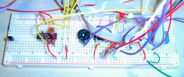
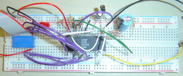
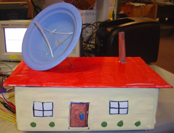
Pictures
P.S. Upon time of demo, we have decrease our bread board from 3 to 2.
Cost Detail
Parts Name Price Vendor Atmel Mega32 8.00 Lab 16x2 LCD 5.00 Lab 4x4 Keypad 5.00 Lab White breed board 5.00 x 2 Lab Winbond ISD1420P Voice Record/Playback IC 5.20 www.futurlec.com (ISD1420P) Magnetic Contact Switch (Closed Circuit) 2.99 x 2 www.smarthome.com (7113) Spy Motion Alarm 5.99 www.smarthome.com (9511) Various resistors, capacitors, wires, LED, 74LS series IC, etc are free of charge. We acquired the smoke detector from home so it is considered free. STK500 and TV speaker is also provided to us in the lab. We have designed our old box using old cardboard boxes, papers, and watercolor dyes. The total cost of our design is 45.17. It is slightly off the budget because we do not know the white breed board cost $5.00 dollar each until the very end. If we know this earlier we would solder our own the board.
Tasks
Here is how our task is divided in our group.
Jimmy Main programming.
Smoke Sensor
Magnetic Contact Switch Circuit
Sound Recording
Buzzer & LED stuff
Report and webYang ISD1420P hardware & specification
Temperature Sensor Circuit
Motion Sensor Circuit
ADC part of the code
(Analog phone circuit, transformer, etc)
House Model
Schematics
Reference
1. Winbond ISD1420 specification
http://www.winbond.com.tw/c-winbondhtm/partner/PDFresult.asp?Pname=922. EPA - Smoke Detector and Radiation
http://www.epa.gov/radiation/sources/smoke_alarm.htm3. 110db Piezoelectric beeper circuit
http://www.imagineeringezine.com/PDF-FILES/beeper.pdf4. LM34 specification
http://instruct1.cit.cornell.edu/courses/ee476/labs/s2004/LM34.PDF5. LMC7111 OpAmp
http://instruct1.cit.cornell.edu/courses/ee476/labs/s2004/LMC7111.pdf6. IEEE Code of Ethics
http://www.ieeeusa.org/documents/CAREER/CAREER_LIBRARY/ethics.html
Legal Notice
All the contents on this pages including the appendix project.c code is owned by Chun-Pai Jimmy Hsieh and Yang Cao. This is copyright material so if you would like to use any of our design or use any of our code.
May 5th, 2004
PDF Format
The PDF format of our report can be download here.