|
|
|
Remote Controlled Outlet Strip |
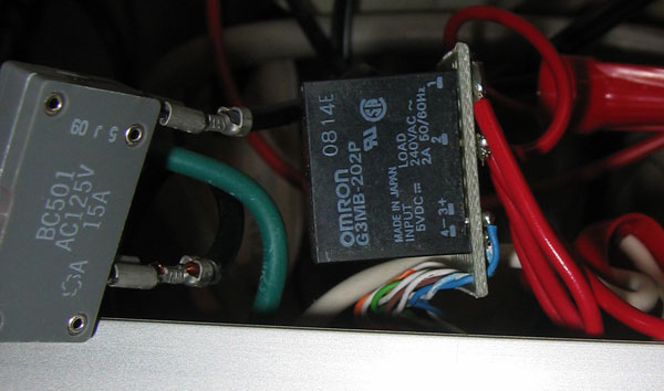
The circuit breaker on the left protected the rest of the world in case something within the box shorted out. The relays on the right were hooked to the microcontroller with Cat5 twisted pair cable, and to the outlets with 16 gauge stranded wire.
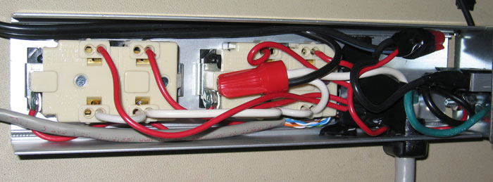
Here's the inside of the strip right before being closed up. There used to be a small switching power supply jammed in there too, but somehow it blew up. So, instead there's a wire coming out that hooks up to an external supply. The relays are covered with electrical tape, right next to the main wire bundle. Interestingly enough, the earth ground wires of the outlets weren't initially hooked to anything, but we fixed that.
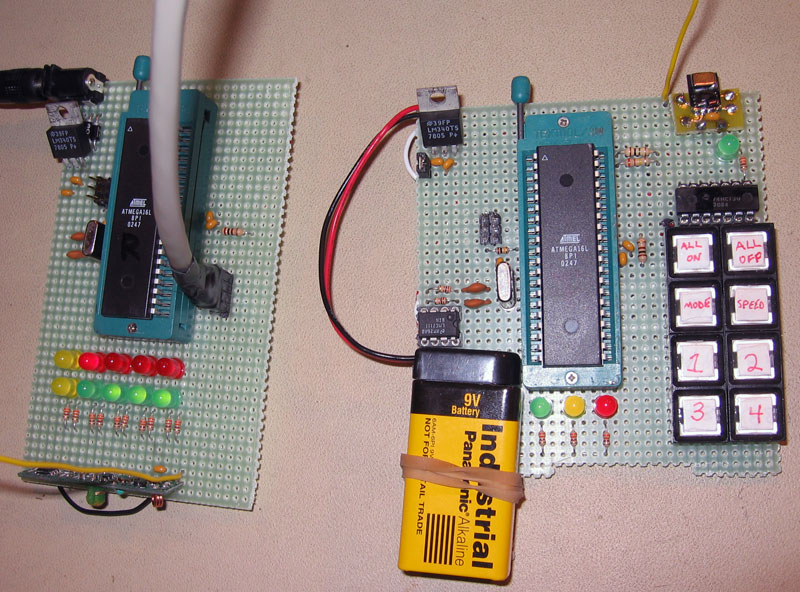
Here are the two circuit boards, transmitter on right and receiver on left. Both used a 17cm piece of wire as the antenna. Transmitter stuff... The battery fits in nicely, so we rubber banded it in. The pin header to the left of the MCU is for programming. The jumper in the upper left corner physically disconnects it from the power supply circuitry. This was also useful for measuring supply current. The 3 LEDs at the bottom are heartbeat, battery low, and battery dead. This was detected by the resistive voltage divider hooked to the analog input. The buttons are just wired to the port, using internal pull-up resistors. They're also connected to the 8-input NAND, which is hooked to the external edge triggered interrupt. The LED next to it lights whenever a button is pressed, to indicate the NAND is functional. The thing in the top right corner is the 433MHz transmitter. Directly above the battery is the op-amp, bringing the UART signal up to the 9V for the transmitter. Receiver stuff... In the top left corner, there's a full wave bridge rectifier before the voltage regulator, so you can plug in any type of 9V supply. The Cat5 cable connected to the pin header on the right goes to the relays. The top yellow LED is the heartbeat, and the bottom indicated when a data packet was successfully received. The rest of the LEDs mirror the status of the relays, green for on and red for off. The thing along the bottom is the 433MHz receiver.
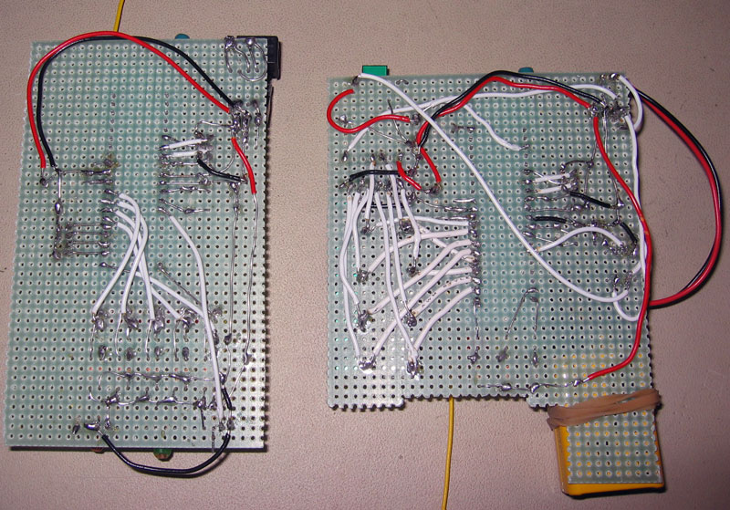
This is the bottom of the two boards. Soldering these two boards was rather tedious and difficult. At least the connections are solid and the wires aren't going anywhere. The only real way to neaten it up is by designing printed circuit boards, but that's a little advanced for this early prototyping stage.
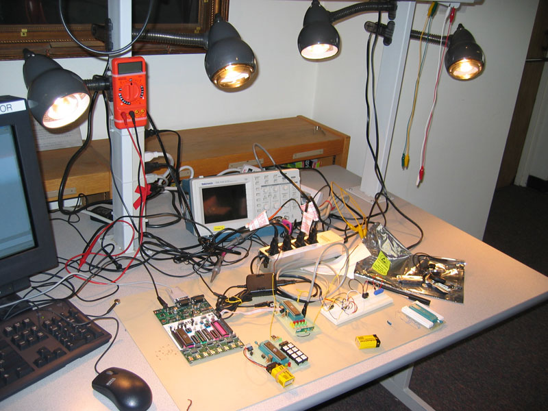
Here's a shot of it all put together. The STK500 is hooked up for
programming, and there's a breadboard for us to test out some new wacky circuit.
We used the 60W lamps in the lab to test the outlets' functionality. They
were easy to come by, and made a good display of the project's capabilities. |
|
|