Perusing through the impressive list of past projects, we decided to make our final project a combination of two technologies—wireless technology and the MP3 player. Specifically, we decided to create an MP3 player that broadcasted the songs to an FM dial. We call this the "MP3 Radio."
To accomplish this, we used an ATMEL ATmega32 MCU, a STA013 MP3 decoder, and an IF VCO MAX2606 FM transmitter as our main hardware components. On our software side, we used C and PHP-GTK as our programming languages; and CodeVision C Compiler and Visual Studio C++ as our compilers.
The user interface consists of two components: one on the PC side, and one on the external hardware piece. On the PC, using PHP-GTK, we created a GUI application, which allowed the user to create the playlist and then start the "broadcast." Externally, on the STK-500, the user can control the MP3 player with the following pushbuttons:
- button 1: (un)pause song;
- button 2: stop song;
- button 3: play song;
- button 4: go to next track;
- button 5: go to previous track;
- button 6: toggle mode (between normal, rock, jazz, & classical);
- button 7: increase volume; and
- button 8: decrease volume.
The flow of how our project works is fairly straightforward. It is outlined by the steps below:
- GUI: The GUI (source code: mp3radio.php), coded with PHP-GTK, generates the playlist. To do this, it merely moves the selected MP3s to a specific directory ".\playlist\." Then, the button "Broadcast MP3s" calls the script serialOut.exe. To compile the PHP, we experimented with several programs. Finally, we found one that actually worked, called PriadoBlender.
- As the name suggests, serialOut.exe (source code: serialOut.c) sends stuff through a serial connection. This is done using COM1. We generated an array storing all the names of all the MP3s in the "playlist" directory. Then, we send each file, character by character, through the RS232 connected to COM1. To do this, we modified a terminal program donated to us by Bob Gardner (@AVRFreaks.net). We set the baud rate to 57,600 bps.
- Our mcu, via the USART interrupt, reads the data sent in from the RS232 from COM1. If a pushbutton is pressed or a song is done playing, the mcu sends the appropriate command to the computer.
- Next, the mcu sends the MP3 data to the decoder. We did not bother buffering our data, because our baud rate is so much slower than the maximum data input rate of our STA013 MP3 decoder, 20Mbits/sec. Moreover, our memory was too small to create a reasonably sized buffer.
- Our decoder outputs the correct clock and data waveforms for our digital to analog converter (CS4334 DAC).
- Finally, the output signal from the DAC is fed into our FM transmitter. Our transmitter can send signals at frequencies between 88.0 and 108.0 MHz.
Figure 1. Diagram of High-level Structure
Hardware/Software Tradeoffs:
The most significant tradeoff involved the limiting speed of the RS-232. We found that, due to the error associated with the higher baud rates (e.g. -3.7% with 115,200 bps), the small amount of memory on the microcontroller, and cycles overheard in C programming, we had to send at a baud rate of 38,400 bps. Thus, we had to encode our MP3s into 32 kbps bitrate MP3s, which is the smallest, lowest-quality possible bitrate for an MP3.
A second tradeoff, as mentioned, is the small amount of memory—only 1 kB of SRAM. Thus, we were unable to effectively buffer the MP3 data before sending it to the STA013 decoder. This means we had to stream the MP3 data from the computer directly to the decoder, which is the reason why we chose a baud rate of 38,400 bps.
Finally, the quality of our songs was compromised by the FM transmitter, which can only transmit in mono. Higher quality songs are possible if we use a stereo-quality FM transmitter chip, which would require transmitting at two different frequencies. Due to our budget and time constraints, we were unable to use a stereo-quality chip.
Relevant Standards:
This topic will be discussed in the Conclusion.
The Software
As aforementioned, we programmed our scripts using C and PHP-GTK. In total, our project requires 3 scripts to operate:- mp3radio.php;
- serialOut.c; and
- serialIn.c.
Mp3radio.php
This first script, mp3radio.php, acts as the user interface for creating his or her playlist. It includes a list of the current tracks on the playlist, and the following buttons:
- "Upload New MP3 File," which opens a file upload dialog box. Users are limited to choosing a *.MP3 file. Once they choose one, the MP3 file copied to a folder called "playlist" (located in the same directory as mp3radio.exe). Then, the list of tracks is refreshed by re-parsing the "playlist" folder for filenames.
- "Remove Song from Playlist," which deletes the highlighted song from the "playlist" folder. Again, the playlist is refreshed.
- "Start MP3 Broadcast (FM)," which executes serialOut.exe using the PHP function exec().
- "Close Program," which exits out of the program.
- killwin() Closes the popup GUI window.
- genPl() Parses the "playlist" directory to return an array of the tracks' filenames.
- fileUpload() Opens the file upload window. The user uses this feature to find songs located in the computer for his/her playlist.
- uploadMP3($fs) Copies the MP3 selected to the "playlist" folder.
- removeSong($list, $plEntries) Removes the highlighted song from the playlist.
- runSerialOut($window) Closes the GUI window and then executes serialOut.exe.
- destroy() Quits the program.
- refreshPl() Refreshes the playlists.
Figure 2. GUI to Make Playlist
SerialOut.c
Of the three scripts, this was the most difficult to write. It took three completely different tries. But, as they say, third time's the charm.
- Try 1: We initially wrote our script based off of the "Interfacing the Serial/RS232 Port" tutorial located at BeyondLogic.org. However, our attempts proved quite fruitless. We soon learned that Windows 2000/NT/XP do not apply port operations to be executed at the application level, due to security reasons. The tutorial at BeyondLogic.org was probably for earlier versions of Windows.
- Try 2:
Next, we wrote a script that utilized IO.dll. This library, theoretically, should've allowed "seamless I/O operations for Windows 95/98/NT/2000/XP." However, due to the lack of documentation, we were unable to successfully send data through COM1.
- Try 3: Finally, we received some aid from a kind fellow from AVRFreaks.net, Bob Gardner. He gave us a C script he wrote that acted as a terminal program, which sent data through COM1 at a baud rate of 9600. This code was very easy to understand and we modified it for our needs. Thus, the current version of serialOut.c was born.
We wrote and compiled this script using Microsoft Visual Studios C++ 6.0. The important functions were...
- void initcom1(void) This initialized COM1 to I/O.
- int auxchk1(void) This function would return 1 whenever a char was received through the serial RS232 connection.
- void main(void) Here, we first initialized COM1 with initcom1() and initialized the playlist with initPlaylistInfo(). Then we sent the first track. After that has been processed, we enter an infinite while loop that incessantly calls controlStates().
- char auxin1(void) This function grabs the incoming char from the serial connection.
- void auxout1(char c) This sends a char through the serial connection.
- void sendMP3(char[]) This function sends an MP3 through the serial connection, specified by the MP3 filename. It will also poll for commands from COM1, and act accordingly—e.g. stop, pause, play, etc.
- void controlStates(void) As the name implies, this regulates and controls the states of the program. In this case, the states signify "current track," "next track," and "previous track." Thus, it regulates what song to send.
- void initPlaylistInfo(void) This function initializes the playlist. It is required before any MP3 can be sent, so that legitimate files will be sent.
We configured our script to work with COM1 and send at a baud rate of 38,400 bps. The theoretical max, 115,200 bps, was tested; however, the error percentage was too large (-3.7%) to yield acceptable results. With 57,600 bps, we found that we lost data (since we couldn't implement a buffer). Thus, we sent our data with a baud rate of 38,400 bps. With this baud rate, we could only send MP3s that have bitrates of 32 kbps. The next lowest bit rate, 42 kbps, equates to 43,008 bps, and already exceeds our baud rate.
This program also contained a state machine, which is controlled by the first 5 pushbuttons on the external user interface, (un)pause, stop, play, next, and previous. Once a song is finished playing, the mcu sends the "next track command" to this program. Thus, as this last statement implies, whether or not a track is complete is not determined on the PC side. This is because, when parsing an MP3 file, the traditional "EOF" (end of file) check cannot be implemented.
This is the microcontroller-side script. Each time data is received, we break into the USART interrupt and send the MP3 data, bit by bit, to the decoder. This script included the following functions... Some code was borrowed from the spring 2002 MP3 project by Nelson Li and Jason Dirner
- void main(void) Like usual, this function calls initialize() first. Then, the STA013 decoder is configured and started by calling the respective functions config_sta013() and sta013_start. If no errors are detected, we proceed into our lovable infinite while(1) loop.
- void initialize(void) This initializes all the global variables. The USART is initialized: it's set to COM1 and a baud rate of 38,400. TIMER0 compare interrupt is set up, PORTB (i.e. the LEDs) is set for output, and PORTA (i.e. pushbuttons) for input.
- void sta013_I2C_start(void) This and the next 3 functions are used when starting up the STA013.
- void sta013_I2C_stop(void)
- void sta013_I2C_read(void)
- void sta013_I2C_write(void)
- void sta013_read(void) This function reads the data stored at a specific address in the STA013.
- void sta013_write(void) This function writes specified data to a specific address in the STA013.
- unsigned int config_sta013(void) This configures the STA013, and returns a 0 for a successful configuration or a 1 if there were errors during configuration.
- void sta013_start(void) This instructs the STA013 to start running.
- void sta013_play(void) This sets the STA013 to playback mode.
- void sta013_stop(void) This ends the playback mode on the STA013.
- void toDecoder(void) This sends the last received word from COM1 to the STA013 decoder one bit at a time.
- void checkSongEnd(void) This determines whether the current track has finished playing.
- unsigned char swapbits(unsigned char x) This is used by toDecoder() to flip the bits, so we can send the bits to the decoder in the order of MSB to LSB.
- void deBouncer(void) This debounces the pushbuttons and executes the buttons' respective commands. It does this by either sending data through the serial RS-232 connection to serialIn.exe (as in for the PAUSE, STOP, PLAY, NEXT, and PREV functions) or by writing values to specific addresses in the STA013 (as in for the MODE and VOLUME CONTROL functions).
The timer0 compare interrupt is used to keep track of time. It is set to trigger each millisecond. This is needed for two functions:
- As in previous implementations, we use this interrupt to control the deBouncer() statemachine.
- The second, not as obvious use, is to check whether a track has finished playing. As aforementioned, we are unable to implement the EOF (end of file) on the PC-side (i.e. check if track is finished from serialOut.exe). Thus, to make up for this setback, we monitor whether the current song has been silent for 3 seconds. We do this using the timer0 compare interrupt (to keep track of the time) and the checkSongEnd() function.
| MODE | Treble (dB) | Bass (dB) |
|---|---|---|
| NORMAL | 0 | 0 |
| ROCK | 0 | 4.5 |
| JAZZ | -4.5 | 13.5 |
| CLASSICAL | -13.5 | -6.5 |
Notice that we've set the rock mode's trebel level to 0 decibels. This is because any positive value of trebel seemed to yield extreme distortion (that was unbearable to the ear).
The Hardware
The hardware consists of the following chips:- STA013 MP3 decoder from STMicroelectronics;
- CS4334 dual 24-bit DAC from Cirrus Logic;
- MAX2606 integrated IF VCO from Maxim-IC;
- MAX884 linear voltage regulator from Maxim-IC;
- ATMega32 Microcontroller from Atmel; and
- 74HC04 Hex Inverter from Phillips Semiconductor.
Figure 3: Block diagram of hardware design
A 14.7456 MHz crystal from Maxim-IC was used along with a 74HC04 Hex Inverter chip. The crystal value matched a standard value used the STA013, which are given as 10 MHz, 14.31818 MHz, and 14.7456 MHz in the datasheet, although other values may be used as well. Initially, we were worried that the discrepancy between the 14.7456 MHz STA013 clock and the 16 MHz MCU clock might cause some problems; however, it seems like the two frequencies are completely independent of each other. The clock circuit is shown in Figure 4 below.
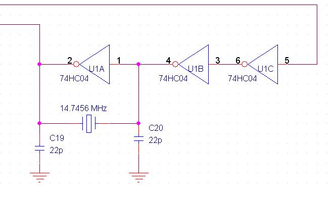
Figure 4: 14.7456 MHz crystal driving circuit
The STA013 is connected to the microcontroller through six pins of PORTC, which are summarized below:
- PORTC.0—RESET
Resets the STA013 before the initialization sequence. RESET must be low for at least 100 ns as listed on the STA013 datasheet. We used a significantly longer RESET period of 1 second.
- PINC.1—DATA_REQ
Input from the STA013, which indicates when the memory buffer is full. This bit can be set such that a ‘0’ indicates a full buffer or a '1' indicates a full buffer, depending on how the DATA_REQ_ENABLE (0x18) register is set in the STA013. We set our register such that DATA_REQ = 0 if more data is needed, and 1 if the buffer is full.
- PORTC.2—SCKR
Data clock signal. Data is transmitted to the STA013 on a low clock signal (SCKR = 0), as shown in Figure 5 below.
Figure 5: SCKR and SDI signal definitions - PORTC.3—SDI
Data signal. Each byte from the MP3 file is read from the USART and passed into swapbits(unsigned char x) to reverse the order of the bits, LSB on the left and MSB on the right. This facilitates the transmission of a byte across the SDI pin since the STA013 requires higher order bytes first.
- PORTC.4—SCL
I2C control clock signal. The I2C data signal is only sent when the I2C clock is low.
- PORTC.5—SDA
I2C control data signal.
Since the STA013 is a 3.3V chip, it is imperative that we maintain a constant, regulated power supply for the decoder within the 2.4 to 3.6V range specified in the data sheet. This was done by connecting the 5V VDD from the MCU to a MAX884 linear voltage regulator (datasheet) to step down the voltage to 3.3V. The regulator uses very little power (on the order of microwatts) and has a low dropoff voltage of 200 mV which ensure longetivity of the circuit). Figure 6 shows a schematic of the MAX844 regulator.
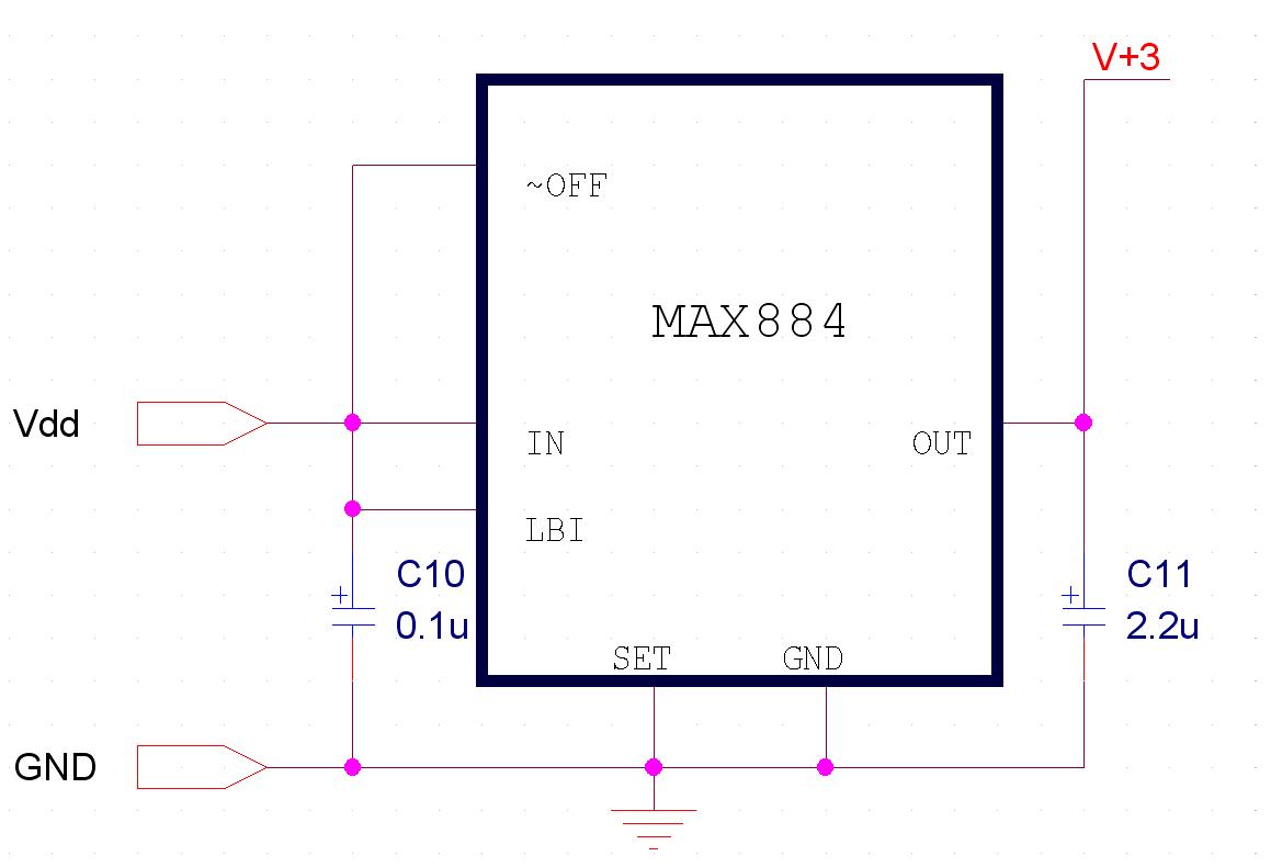
Figure 6: MAX884 voltage regulator circuit
Also, it is important that none of the 5V pins are connected directly to the 3V chip, as forewarned on the PJRC website, which requires bi-directional level shifting. Essentially, we connect the SCL, SDI, SCKR, and RESET pins to PORTC through a 4.7 kOhm resistor and a 47 pF capacitor in parallel, as shown in the following figure taken from the PJRC website.
Figure 7: Bi-directional level shifting for SCL, SDI, SCKR, and RESET pins
(Source: http://www.pjrc.com/tech/mp3/sta013.html)
Essentially, the 4.7 kO resistor and 47 pF capacitor serve to drive the input pin on a rising edge and limit the steady-state current to less than 0.5 mA. The capacitor is especially important since the data and clock pins must be driven rapidly (over 1 MHz). The SDA signal can be similarly connected using the following scheme.
Figure 8: Bi-directional level shifting for SDA pin
(Source: http://www.pjrc.com/tech/mp3/sta013.html)
The 4.7 kOhm pull-up resistor to 3.3 V is needed to satisfy the 2.0 V CMOS input high requirement, whereas the 270 O resistor limits the current into the STA013 SDA pin.
Since the STA013 is a SOP28 pin with 0.5 mm leads, it could not fit directly into a proto-board or standard solder board. Even though Aries Electronics sells a 32-pin SOIC-to-DIP adapter, which can be obtained from Digikey (P/N: A323-ND), the $10 cost was beyond our budget; therefore we were left to make our own 28-pin adapter. We were initially hesitant about soldering the 28-pins onto our custom adapter or wire leads due to the cost of the chip; instead, we used two large clips to press the leads down on the pins to achieve adequate connections. However, this did not work …
We initially soldered resistor leads, which are thinner than the normal enamel-coated copper wires in lab, onto a small solder board. Since the holes are spaced about 1 mm apart, we really only had to adjust the pins that went in between them. Needless to say, this was not an easy soldering job, and trying to pin the leads down on the chip took even more time. Eventually, with less than week left before our demo, we decided to redesign our adaptor, this time using wires instead of resistor leads. Again, we found that the only way to achieve adequate connection between the pins, which is crucial for high-frequency signals such as the clock pins, is to solder all 28 pins. With this done, we now have our custom-built 28-pin SOIC-to-DIP adaptor, as shown in the figure below.

Figure 9: Completed adapter design (those are not antennas!)
Figures A and B below show the STA013 and CS4334 schematics as obtained from the PJRC website. Separate 5V and 3.3V power rails were maintained in order to provide the 3.3V VDD for the STA013 and the 5V VDD for the CS4334.
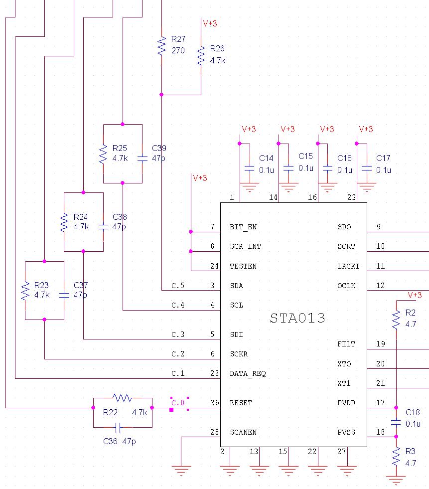
Figure 10: STA013 wiring schematic
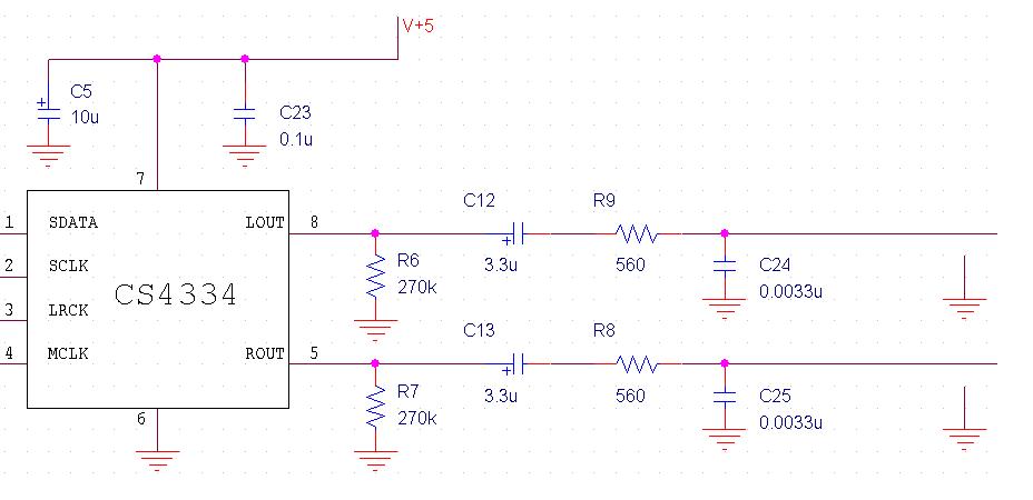
Figure 11: CS4334 wiring schematic
The FM transmitter part of the circuit has a two-channel input which is subsequently summed to create a mono signal. The MAX2606 VCO is used because it provides high-reliability, low-power transmission capabilities in the 70 to 150 MHz frequency range. It contains an integrated varactor to act as the tuning capacitor, which when coupled with an external inductor, provides the necessary oscillation.
The nominal oscillation frequency is set primarily by the external inductor, which is specified at 390 nH on the Maxim website. However, we quickly found out that despite our compact soldering job, the parasitic capacitance of the wire and element leads decreased the oscillation frequency to only 40 MHz, far too long for the FM band. Therefore, we had to scrap the standard 390 nH inductor and create our own using wire coils and a 3 mm diameter core. The following website gives a good tutorial on making your own air-coil inductors, http://sound.westhost.com/project54.htm, which gives the approximate inductance value as
L = N2 * r2 / (228r + 254l)
Where L = inductance (µH), N = number of turns of coil, r = average coil radius, and l = coil length. All dimensions are measured in mm.
The oscillation frequency increases linearly (roughly) as the inductance decreases; therefore, we aimed for a nominal inductance of two-thirds to half of the specified value. This value can later be tuned by simply varying the spacing of the coils. Our resulting inductance is 280 nH which places the center frequency at just over 100 MHz. The frequency can also be tuned using a 100 kO potentiometer connected to a pull-up resistor to VDD and GND. The 10 kO potentiometer shown in the figure below adjusts the attenuation along the two channels, essentially attenuating signals to below 60 mV in order to reduce distortion.
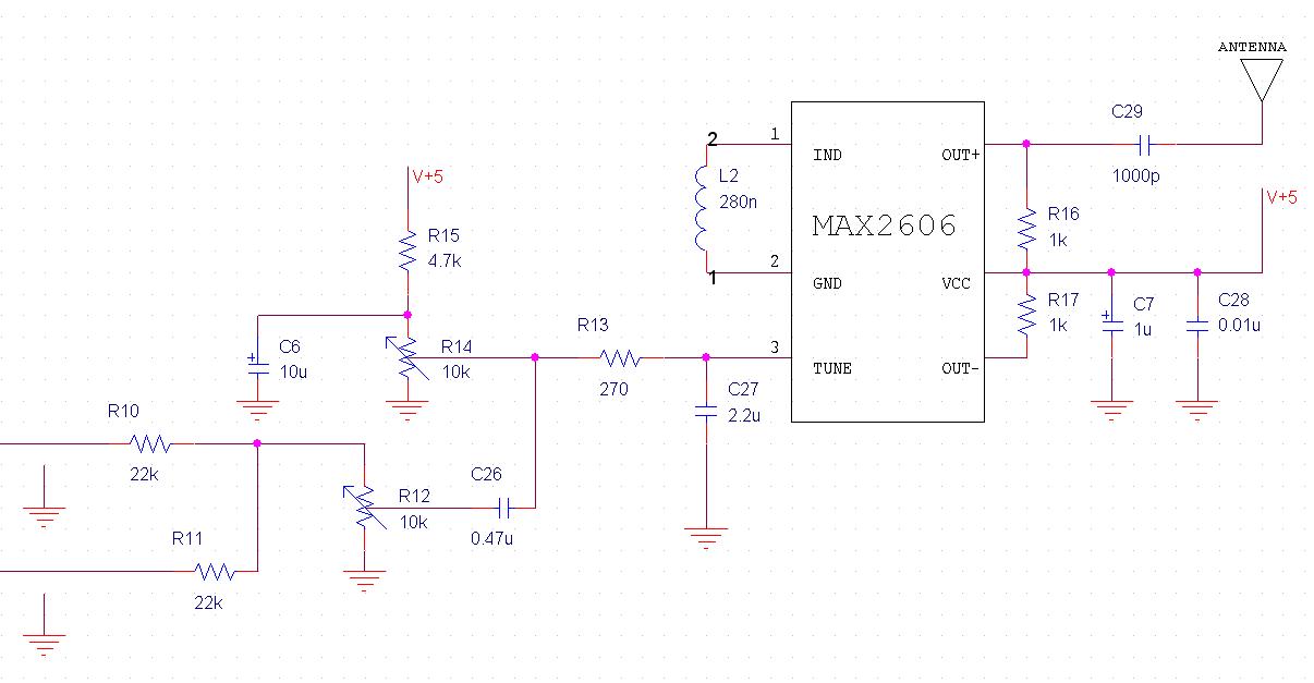
Figure 12: MAX2606 wiring schematic
More information about the FM transmitter can be found on the MAX2606 datasheet. A very short antenna was used during testing to prevent an possible interference with FM radio stations or other groups. However, a longer steel antenna can be attached to increase the quality of the transmission. Either way, the transmission distance for a normal MP3 input is no more than a few feet from the antenna, which has been tried and tested in the lab. Figure 13 below shows the FM transmitter, conveniently hanging from the lab bench.

Figure 13: FM transmitter circuit
The overall schematic of our circuit is shown below:
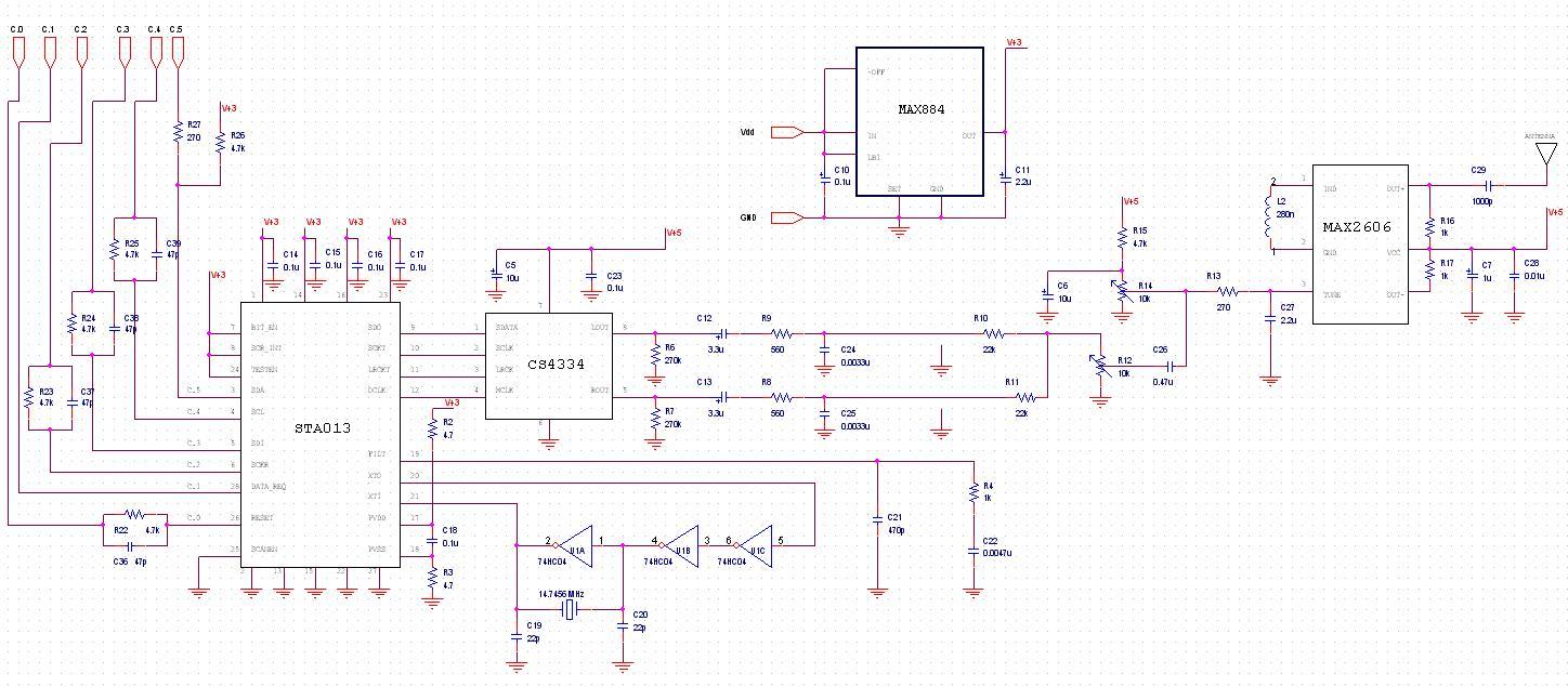
Figure 14: Complete wiring schematic
The overall analog design contained several components, which are all connected using wire clips. Ideally, we would have liked to move all the major components (STA013/CS4334 decoder, MAX2606 transmitter, ATMega32 MCU, and 14.7456 MHz clock circuit) onto the same board to reduce parasitic impedances and increase the robustness of the circuit. This would also require a lot fewer wire clips, which may facilitate the debugging process ...
- An user-friendly computer interface that could send a playlist of MP3 files to the an external microcontroller via the RS-232.
- An external, pushbutton-based user interface that would control the MP3 player.
- A fully functional MP3 decoder and 24-bit audio-quality DAC.
- A compact FM transmitter with frequency control over the FM band (88.0 MHz to 108.0 MHz) and volume control.
- Volume control from the pushbutton interface.
- Mode control from the pushbutton interface.
With the STK-500 and our hardware/software bundle, anyone with a computer (Windows OS 2000+) will be able to use our MP3 radio. During our lab sessions, we did not experience any interference with other projects, because we had limited our FM transmission distance to within a few feet. Also, there were no other groups that we knew of that transmitted between 88 MHz and 108 MHz.
Here's some great advice... Don't build your own adapter! =) Why? Well, a picture is worth a thousand words...

Figure 15. Kudos to Jian
What we could've done differently
- Buy a SOIC-to-DIP adaptor.
- Increase the FM transmission distance.
- Increase our RS-232 baud rate with error-checking to allow higher bitrate-quality MP3s.
Relevant Standards/Ethical Considerations
This design process and specifications are required to meet the following set of standards and codes:
- IEEE Code of Ethics;
- EIA RS-232;
- MP3 (MPEG-1 Audio Layer-3);
- Federal Communications Committee (FCC); and
- Recording Industry Association of America (RIAA).
The RS-232 standard defines the serial connection from the PC serial port to the base station using a standard male-female DB25 (or D9) connector as defined. The standard lists several parameters such as:
- A "Space" (logic 0) will be between +3 and +25 Volts;
- A "Mark" (logic 1) will be between -3 and -25 Volts; and
- The region between +3 and -3 volts is undefined.
A series of baud (or bits per second data transmission rate) rates are also specified, with a maximum of 115,200 baud under the new RS-232D standard. More information regarding the RS-232 standard may be found on the 476 Course Page or this Beyond Logic site.
MP3 defines the audio compression/encoding standard originally developed by the Motion Picture Experts Group (MPEG) and formalized by ISO. The MP3 takes advantage of several compression schemes, such as Joint Stereo and Huffman coding, to compress the audio file into one twelfth its original size while preserving its original sound quality. Encoding the MP3 file requires careful consideration of the following three parameters:
- Channel type (either stereo or mono). In general, a stereo encoding is of higher quality and is more reliable, but doubles the size of the MP3 file. Our project used a mono signal to reduce the size of the MP3 file in order to transmit it over the RS-232 port.
- Sample frequency: This defines the number of samples taken per second. A higher sample frequency corresponds to higher reproduction quality but with larger size. We used sample frequencies of 44,100 Hz (44,100 samples per second), 22,050 Hz, and 11,030 Hz to encode our files.
- Bitrate. This specifies the quality of the MP3 file in a digital format, i.e. using bit values. A larger bitrate gives higher reproduction quality. Standard CD-quality MP3 files is 192 kbps, whereas our bitrate was only 32 kbps. More information about the MP3 standard may be found at Paolo Corsini’s website, including a table of bitrate versus compression ratios.
The FCC was established by the Communications Act of 1934 and is charged with regulating interstate and international communications by radio, television, wire, satellite and cable. In this particular application, the FCC rules and regulations govern the output power and broadcast frequencies of AM and FM (88.0 to 108.0 MHz in the United States) radio transmissions. The complete set of FCC regulations can be found in the U.S. Code of Federal Regulations 47CFR Part 73 (MIT website with links); however, to summarize, each channel has a bandwidth of 200 kHz and can pass audio and subcarrier frequencies up to 100 kHz. Deviation is often limited to 150 kHz total in order to prevent interference to adjacent channels/stations on the band. Stations may go up to 10% over this if they use stereo or other subcarriers (online dictionary with definition). In designing our FM transmitter, we must be careful not to interfere with radio broadcasts on the FM band, which mainly involves decreasing the output power to reduce the transmission distance and tuning the frequency to an unused portion of the FM band. Fortunately, the MAX2606 RF VCO chip broadcasts with an output power of -21 dBm into a 50 Ohms load (much less than the maximum acceptable emission of 10 dBm).
Due to the compact nature of MP3 files, they are often distributed and used in a manner that violates copyright laws. In fact, the illegal online distribution of audio tracks continues to be a major legal battle for the RIAA and accused “music pirates.” Since our device deals with the transmission of MP3 encoded audio files, it is important that we minimize any possibility for outside agents (i.e. another receiver nearby) to eavesdrop on the FM transmission. This may be in direct violation of the IEEE Code of Ethics and many copyright laws. Furthermore, since we encoded MP3 files directly, the user must be aware of all copyright issues and potential legal actions associated with the files.
IEEE Code of Ethics
It is imperative that our design meets all requirements stated in the IEEE Code of Ethics, particularly the following codes:
- To accept responsibility in making engineering decisions consistent with the safety, health and welfare of the public, and to disclose promptly factors that might endanger the public or the environment.
We had to make sure that our broadcasts over the FM (88.0 to 108.0 MHz) band did not interfere with other radio transmissions, which may adversely impact the environment for other people. Just imagine you’re listening to your favorite song on the radio, and suddenly, some random, lewd song comes out of nowhere. We limited any possible interference by reducing the size of our transmitting antenna and output power so that our maximum transmission distance is only a few feet.
- To be honest and realistic in stating claims or estimates based on available data.
We notify the user outright that our prototype MP3 radio is only capable to transmitting low-quality (32 kbps), mono-channel MP3 files due to reliability issues with the RS-232 protocol. Currently, we only send data at 38,400 baud, instead of the maximum 115,200 baud. We hope to increase this capability in future releases in order to provide better quality MP3 songs, but for the present, we are completely honest and realistic in stating our capabilities.
- To maintain and improve our technical competence and to undertake technological tasks for others only if qualified by training or experience, or after full disclosure of pertinent limitations.
We focused on our core areas of expertise—Dave did a tremendous amount of work with the PC interface, RS-232 communication protocol, and MCU state-machine implementation, while Jian focused on the FM transmitter, STA013/CC4334, and analog interface designs. Both of us did a lot of research on these areas before implementing them in order to augment our technical competencies.
- To seek, accept, and offer honest criticism of technical work, to acknowledge and correct errors, and to credit properly the contributions of others.
We were always open to suggestions from Professor Land, the lab TA’s, and other ECE476 students, particularly in the planning stages of the project. We initially proposed transmitting MP3 files at 433/900 MHz to a set of wireless headphones or speakers, but quickly found out the technical difficulties of such a project given our current constraints. From there, we worked with Professor Land to reorganize our project and with the TA’s along the way to check our progress.
- To assist colleagues and co-workers in their professional development and to support them in following this code of ethics.
Like many of the other groups, we were always willing to help out other groups if needed; we were always truthful and realistic about our suggestions and answers. The soldering line was always a problem, particularly late in the semester, so we tried to be as efficient as possible and always yielded the seat to other groups as soon as we were done.
Intellectual Property Considerations
We had used some code from a previous year's group, as mentioned above. Moreover, we were given a terminal program, written in C, by a Bob Gardner. In both cases, we gave the original authors' credit for their work. The design of the FM transmitter circuit is found on the MAXIM-IC web site; and similarly, the design for the MP3 decoder was obtained from the PJRC web site.
Special Thanks
We would like to thank Professor Land for helping us so much throughout the course of the semester, particularly with all the sage advice given during lab, and for helping us solder the CC3443 24-bit decoder and MAX2606 RF VCO chips onto respective surfboards. Also, we would like to thank our lab TA’s, David Li and Jeannette Lukito for all their help. This course would have been a lot harder if not for their help on our lab problems. Finally, we’d like to thank MAXIM-IC, Analog Devices, and Fairchild Semiconductor for supplying us with sample chips, Paul Stoffregen of PJRC for a remarkably helpful page on the STA013 without which we would have been completely lost, and Chris Lehmann for helping us solder part of our MP3 decoder circuit.
- mp3radio.exe (source: mp3radio.php)
- serialOut.exe (source: serialOut.c)
- serialIn.c
- zip of PHP & PHP-GTK DLL files:
| iconv | intl | libgdk-0 | libglib-2.0-0 | libgtk-0 |
| mmcache | php4ts | php_gtk | libgmodule-2.0-0 | |
Cost
| Item | Manufacturer | Part Number | Cost |
|---|---|---|---|
| MP3 Decoder | STMicroelectronics | STA013 | $12 |
| 24-Bit DAC | Cirrus Logic | CS4334 | $5 |
| Shipping & Handling | PJRC | $5.18 | |
| 14.7456 MHz Xtal | Maxim-IC | SE3431-ND | $0.96 |
| Solder Boards | Professor Land | $2.50 (x1 large) $2.10 (x3 small) $4.90 |
|
| Surf Boards | Professor Land | $10 | |
| ATMega32 | Atmel | ATMEGA32-16PI | $0 (free sample) |
| Voltage Regulator | Maxim-IC | MAX884 | $0 (free sample) |
| IF VCO | Maxim-IC | MAX2606 | $0 (free sample) |
| Resistors & Capacitors | Digital & Analog labs | free | |
| 8-pin, 14-pin sockets | Analog lab | free | |
| STK-500 | Digital lab | free | |
| 16 MHz Xtal | Digital lab | free | |
| Total: | $38.04 | ||
Links
These awesome sites saved us countless hours.
- PJRC “MP3 Player, Using The STA013 Chip” by Paul Stoffregen;
- STA013 data sheet
- Past 476 MP3 projects (especially these two);
- MAX2606 45MHz to 650MHz, Integrated IF VCOs with Differential Output;
- MAX884 3.3V Low-Dropout, Low-IQ, 200mA Linear Regulator with Standby Mode;
- ATMega32 datasheet;
- AVRFreaks.net forum;
- PHP & PHP-GTK; and
- PriadoBlender.
Random pictures

Figure 16: Patented 3D Design |

Figure 17: Dave Chai at the Computer, working hard
|
