Created by Eric Chin and Mingbo
Zhao
Introduction
Our project is an autonomous toy
car that tracks a high pitched audio signal. Using two microphones, a
microcontroller, and two DC motors on an existing remote controlled car and, we
implemented our own control logic to detect high pitched 3.5kHz audio signals and drive the car.
This project consists of both software and hardware
designs. Starting from the high level point of view, we divided this project
into three components: Signal Processing Unit, MCU and Motor Control Unit. Based
on the functionalities of our projects, we made a Signal Processing unit that
can identify the existence of a sound source and convert the intensity of the
sound into a measurable voltage level. Thus, our “blind bot” will be able to firstly hear the sound, secondly
distinguish the intensity of the sound which indicates the distance of the sound
source and receiving unit, and lastly position the sound source with a
reasonable accuracy. The MCU is designed by taking the voltage generated by the
Signal Processing Unit which basically tells where the sound source is, then
output the control bits to regulate the Motor Control Unit. Since our “blind
bot” should be able to move forward and make
left/right turns, we have two motors included in the Motor Control Units. By
controlling a switch, we are able to turn on/off the back motor, and by using an
H-bridge we are able to control the three movements of the front motor: turning
left, turning right, and stop.
High Level Design
Our motivation for this project came arose from the DARPA Grand
Challenge, a national contest to create an autonomous ground vehicle that would
successfully complete an obstacle course. We decided that a scaled-down version
of this challenge would be appropriate for our final
project.
The major math components in this project arise from our Signal
Processing Unit, in which we designed a bandpass
filter to pass the 3.5kHz audio signal and filter out
noise at other frequencies. We combined a sequence of lowpass and highpass filters to
act as a bandpass filter centered at 3.5kHz frequency, with cutoff frequencies of 1kHz and 5 kHz.
Another calculation involved is the amplification from the RMS-to-DC converter.
Since the signal from the integrator is typically under 10mV, we made an
amplifier using LMC7111 opamp chips with a gain of
roughly 500. Therefore the output from the signal processing unit is in between
1 to 5 volts.
Our autonomous car has two microphones to detect a 3.5kHz audio signal. We measure the intensity of these two
signals using a RMS-to-DC converter and connect them to our Atmel Mega32
microcontroller (MCU). The MCU takes analyzes these two input signals and
outputs 3 signals to drive the motor attached to the rear wheels, and one signal
to drive the motor attached to the front wheels.
After testing our project with the real 12V power source (8 AA
Batteries), we discovered that we could not use pulse width modulation (PWM) to
drive the front and rear motors at the same time – the 12V power source could
not deliver enough power. We decided to use only one H-bridge to drive the front
motor (turning the car left and right) and use another circuit to drive the rear
motor.
There are no known standards that are related to our project. Our sound
source, a 3.5kHz high pitched audio signal is in the
range of auditory signals which are not restricted, except by noise level, in
certain communities. Our sound source is definitely not loud enough to violate
any noise ordinances.
Hardware Design
The autonomous car we built runs
on two power supplies. A 9V battery is connected to a 5V regulator (LM340) to
power the microcontroller, microphones, amplifiers, and RMS-to-DC converters. A
12V power supply powers the H-bridges and motors.
Two microphones on the toy car receive audio input. We connect each of
the microphones to a band pass filter with a pass band including 3.5kHz. The filtered signals are passed to a RMS-to-DC
converter (AD636), and the outputs of our RMS-to-DC converters are amplified and
fed as inputs to the MCU.
The MCU is connected to two different circuits that drive the front and
rear motors. The MCU outputs 3 different signals (PWM, DIR, BRAKE) that are optoisolated using 4N35 transistors. This
isolation is necessary to prevent voltage spikes from the motor’s power supply
to wipe out transistors on the MCU. We connect these optoisolated signals to an
H-bridge, which enables the front motor to be driven in both directions,
allowing the car to turn left and right. The two outputs of the H-bridge are
either at 0V or 12V, but we discovered that a 12V voltage drop across the front
motor was starting to burn the motor out. We connected two 5V voltage regulators
(LM340) to the output to restrict the output voltages to either 0V or 5V. We
connected the two leads of the front motor to the output terminals of the
voltage regulators.
The
MCU also outputs another signal, also optoisolated in the same manner, to drive
the rear motor. We connect the rear motor in the circuit shown below. When the MCU outputs 5V, the motor turns on and the car moves
forward. This circuit uses the same design as Lab5 of
ECE476.
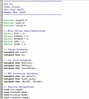
Program Design
When the MCU boots up, we
initialize timer 1 to run at 250kHz and to interrupt on
an output compare match value of 249. With these settings, our timer 1 Output
Compare Match ISR executes every 1 ms. This ISR
decrements a variable time1, which is used to flash a LED connected to the
microcontroller to indicate the microcontroller is
running.
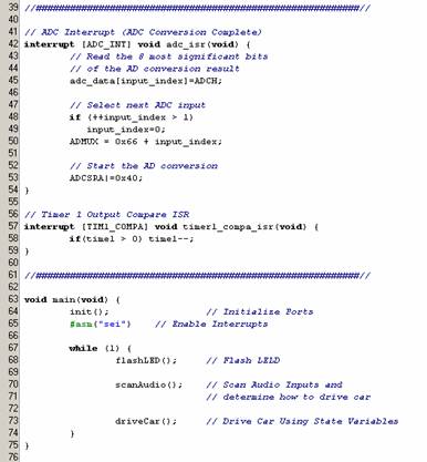
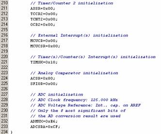
The
ADC is also initialized at startup to run at its slowest frequency (125 kHz) and
to use AVcc (connected to 5V) as the ADC voltage
reference. Thus, voltage to ADC conversion result is given by ADC = VIN * 256 /
VREF, where VREF is 5V. We enable the ADC
conversion complete interrupt. In our ADC Conversion Complete ISR, we store the
latest result into an array named adc_data, switch input channels
(we need to continuously sample the intensity of the two microphones), and start
the next ADC conversion.
After the MCU is initialized and interrupts are enabled,
the microcontroller enters into the heart of the program, our endless loop which
continuously runs 3 functions. Our first function flashLED() in the loop flashes the LED using the
time1 variable to detect the number
of milliseconds that have elapsed since the last flash. Our second function
scanAudio()takes the last ADC conversions from the
audio inputs and analyzes them to determine how to drive the car. Our last
function driveCar() uses state variables to drive and
steer the car.
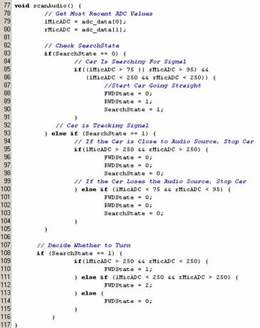
Function scanAudio() takes the latest ADC conversions from
the left and right microphones. The variable searchState indicates whether the
car is tracking an existing signal or searching for a signal. If the car is
searching for a signal and detects a signal above a certain threshold, we start
the car going forwards. Otherwise, the car remains stopped. If the car is
already tracking a signal, and the signal falls out of range, we stop the car.
If the signal becomes too strong, we assume the car has reached its destination
and stop the car. We only turn the car when the car is moving. We analyze the
intensity of the signals to determine if the car should
turn.
Function driveCar() uses the state variables FWDState, and
RWDState,
which are set in scanAudio() to drive the motors. FWDState indicates the desired state of the
front motor, and RWDState indicates the desired
state of the rear motor. Recall that an H-bridge, requiring 3 inputs, drives the
front motor. Thus, we send the correct PWM, DIR, BRAKE bits to the H-bridge
when we want the car to turn left, right, or continue going straight. Recall
that we drive the rear motor using the circuit shown in Figure 1. Thus, we sent
out a logical high if we want the car to go forward and a logical low for the
car to stop.
We had originally setup our program to output two PWM signals coming from
Timer 0 and Timer 2 of the MCU that drives two H-bridges. We simply changed the
OCR values to change the duty cycle of our square waves that drive the DIR input pins of the H-bridges. Because
the 12V batteries could not supply enough power to drive the motors, we had to
change the code in driveCar() to drive the motors using logial low and high values of output port
pins.
We did not borrow any code from anyone else, but we did use Codevision’s source code generator to initialize all the
relevant registers in the MCU.
Results
Our autonomous car tracks our
signal at a range of 1 to 2 feet when our buzzer is driven with a 9V battery. If
the audio source moves out of range or the audio source stops emitting a signal,
the car stops. Every part of this project worked as expected. We did not see any
issues affecting its speed of execution, and the car was able to accurately
track the signal by analyzing the microphone signals.
Safety is taken into concern because the car stops moving if it cannot
sense an audio signal. This way, the car will not hit anything in the absence of
a tracking signal. We also created a bandpass filter
and set high thresholds in our program to isolate noise so the car does not move
on any random loud audio signal. However, because our car is “blind,” the car
will run into objects. An extension of this project would be to eliminate the
chance of hitting any objects by adding infrared distance sensors to the
car.
We did not see any interference from other projects in the lab. Few
people were emitting loud noise signals at that frequency. Due to the
sensitivity of the microphones, the microphones do not pick up signals more than
3 feet away. While we characterized the response of the microphones, we
determined it was not vibration sensitive.
This autonomous car is very easy to use. It requires 6 AA batteries and 1
9V battery. All the user needs to do is to create an audio signal at 3.5 kHz and
the car will follow the signal at a range of a few feet.
Conclusion
We enjoyed working on this
project and seeing the car work as expected. The range of our microphones was
not as great as we expected – it would only pick up signals from a few feet
away. The other microphones we tested also were not very sensitive. If we had a
bigger budget, we would choose a more sensitive microphone and increase the
range of the car so it could track a signal further away. Also, we would choose
a tracking signal at a friendlier frequency – our 3.5kHz signal was too high pitched. It was very annoying to
listen to that signal for extended periods of time.
This project did not have any relevant standards, as communication only
occurred via a signal in the auditory range. We reused circuitry from Lab 5,
ECE476, which is publicly available on the Internet. We used Codevision C to generate code to initialize the registers on
the MCU – this software is licensed for Cornell usage so there is no IP
concerns.
We took into account ethical issues while creating this project.
Specifically, we have addressed these points from the IEEE Code of
Ethics:
1.
to accept
responsibility in making engineering decisions consistent with the safety,
health and welfare of the public, and to disclose promptly factors that might
endanger the public or the environment
We
ensured that our car moves at a speed that is easy to control and that our
autonomous car stops moving whenever the car cannot sense an audio
signal.
2.
to be honest
and realistic in stating claims or estimates based on available
data;
We
disclosed accurate results through testing and did not reuse code or hardware
designs without citing those sources.
3.
to
reject bribery in all its forms;
All the free
samples that we obtained were for testing and development purposes. We did not
enter into any agreements with the companies that supplied us with parts or
people who supplied us with help.
4.
to
improve the understanding of technology, its appropriate application, and
potential consequences;
The purpose
of this project is to demonstrate the capabilities of an autonomous car. Car
manufacturers and the military are trying to make their vehicles autonomous.
This project shows that it is possible and shows the safety and technical
concerns that need to be taken into consideration.
5.
to
assist colleagues and co-workers in their professional development and to
support them in following this code of ethics
We
assisted other group members in their lab with their projects whenever they
needed consulting help.
Appendix: Program
Listing


Appendix:
Schematics
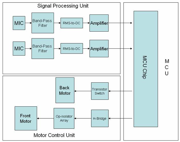
Figure 1:
High Level Diagram
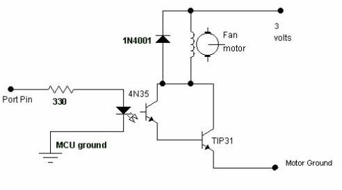
Figure 2:
Back Motor Driver Circuit
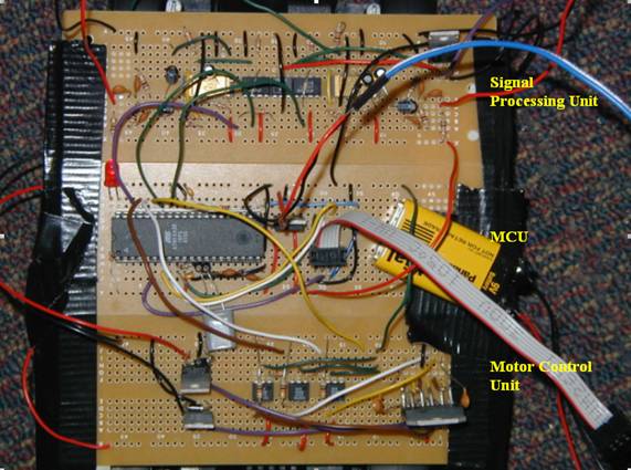
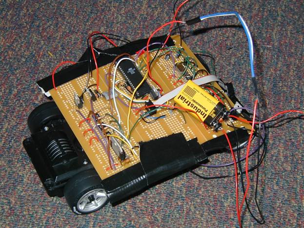
Figure 3:
Hardware Circuitry
Appendix: Cost
Details
|
Quantity |
Item
Description |
Samples? |
Unit
Cost |
Total
Cost |
|
1 |
Atmel Mega32
MCU |
|
$8.00
|
$8.00
|
|
3 |
Big Solder
Boards |
|
$2.50
|
$7.50
|
|
2 |
Horn Microphones
(359-1007-ND) |
|
$1.11
|
$2.22
|
|
1 |
Piezzo Buzzer
(302-1120-ND) |
|
$3.36
|
$3.36
|
|
4 |
Fairchild 4N35
Optoisolators |
LAB |
$0.00
|
$0.00
|
|
1 |
TIP31 NPN
BJT |
LAB |
$0.00
|
$0.00
|
|
2 |
Analog AD636
RMS-DC Converters |
YES |
$0.00
|
$0.00
|
|
1 |
National LMD18200
H-Bridge |
YES |
$0.00
|
$0.00
|
|
3 |
National LM340 5V
Regulator |
LAB |
$0.00
|
$0.00
|
|
2 |
National LMC7111
Op Amp |
LAB |
$0.00
|
$0.00
|
|
1 |
Old RC Car
(including Stepper Motors) |
|
$0.00
|
$0.00
|
|
|
|
|
Total |
$21.08
|
Appendix: Task
List
|
Task |
Eric |
Mingbo |
|
Project
Description |
X |
X |
|
Ordering
Parts |
X |
|
|
Microphone,
Filter, Amplifier, RMS-DC Testing |
|
X |
|
H-Bridge
Testing |
X |
|
|
MCU Program
Development |
X |
X |
|
Soldering |
X |
X |
|
Hardware
Integration |
X |
X |
|
Final
Report |
X |
X |
Appendix:
References
Spring 2004
ECE476 Website: http://instruct1.cit.cornell.edu/courses/ee476/
Datasheets:
National
Semiconductor LM340 Datasheet
National
Semiconductor LMC7111 Datasheet
Fairchild
Semiconductor 4N35 Datasheet
Fairchild
Semiconductor TIP31 Datasheet
Analog
Devices AD636 Datasheet
Thanks to
Bruce Land, Jeannette Lukito, David Li, and all 476
TAs for their consulting help!