
Is Your Pitcher Half Full
or Half Empty?
Introduction | High Level Design |
Program and Hardware Design | Results of the Design | Conclusions
| Appendices |References |
Pictures
Matt Aizcorbe and Erin McClure
We created a wireless device to affix to the bottom of a pitcher that
alerts the wait staff when the pitcher is empty.
We used the a priori knowledge that when a pitcher is empty the
pitcher’s bottom is perpendicular to the ground. By affixing an accelerometer to the bottom of a pitcher we can
detect the angle of the bottom in relation to the ground. There is a direct correlation between the
maximum angle the pitcher has reached and the volume still in the pitcher. We use this fact to monitor the pitcher’s
volume through a wireless connection.
The signal from the accelerometer is transmitted at 433MHz directly from
the pitcher to the server station. The
server station consists of an LCD and an array of control buttons that reset
the meter, change the table number, and reset the pitcher count.
Rationale
Our decision to
create the beverage monitor for our project was due to a combination of
factors. The stroke of genius came when
Background Math
We monitored the
tilt of the pitcher using the duty cycle output of our accelerometer. The MCU measures the rising edge pulse
width, T1, and the total length of the duty cycle, T2. The acceleration is calculated by the following
equation:
![]()
Then the arcsine of
the acceleration is taken to find the angle of the tilt. This angle correlates to the volume of the
pitcher.
In order to minimize
the influence of invalid angle readings as a result of the wireless connection,
![]()
Y(t) is the
calculated angle, x(t) is the current angle reading, and y(t-1) is the
previously calculated angles. The
parameter α was determine through trial and error during testing.
Logical Structure
Our overall project design can be reduced to three specific states that
can be seen in the state diagram below.
The first state, the state entered at the beginning of the programs
execution, is the Set Table state. In
this mode the wait staff can select the table that they are serving. The selection is made by using two buttons,
one to increment the table number and one to decrement it. Once the correct table is selected, the
enter button is hit and the program then goes into Monitor mode. In this mode the wireless device on the
pitcher sends the signal from the accelerometer to the server station. At the server station, the wait staff can
see the number of the table being served and how many rounds have been served
to the table. There is also a status
bar showing the status of the pitcher’s volume. The MCU at the server station uses the signal from the pitcher to
calculate its volume. In this state,
there is a reset button in case a different table is about to be served. Unless the reset button is pressed, the
program will stay in this state until the pitcher is empty. Once the signal indicated the pitcher is
empty, the last state, the Refill state, is entered. Here the server station indicates that the table needs a
refill. Once the wait staff refills the
pitcher they press the enter button and the project returns to the Monitor
state, and the additional round is indicated on the display. The reset button can also be used in the
Refill state if the table decides not to go for another pitcher.
When we implemented the receiver and transmitter our results were less than
perfect. The problems occurred as a
result of noise and antenna related issues.
There were both hardware and software solutions at our disposal. We first tried hardware when we found that
the edges in the output signal of the receiver were not as square as we had
hoped and this adversely affected the input capture mode.
Later we found that we were getting invalid angle readings that were due
to noise and interference with our transmissions. We could have implemented a hardware filter but instead
The FCC sets aside frequencies between 420 MHz and 450 MHz for Amateur
use, thus we are complying with the standard by transmitting our signal at
433MHz.
Existing Patents and Intellectual Property
We have been able to find technology developed by Mitsubishi Electric Research Laboratories
that has been developed for the same function as our beverage meter. However, our solution to the problem uses
completely different technology, thus we would not have a problem with existing
patents, copyrights, or trademarks.
Using an accelerometer was an original idea that has not previously been
implemented.
Software Design
For our project,
software is used for two specific purposes, reading and calculating the
orientation of the pitcher and providing a user interface for the LCD at the
server station.
In order to measure
the length of the rising edge pulse and the total length of the duty cycle, we
use the Timer 1 input capture mode.
This mode triggers an interrupt on a rising or falling edge on pin D6,
depending on the control settings.
Along with triggering an interrupt, the capture mode saves the value of
the timer 1 into a reserved register.
In our specific interrupt we first read the value from the reserved
register. This was tricky to code
because the counter value is in a 16 bit register and the MCU only has an 8 bit
bus. It turns out that when reading 16
bit registers the lower half must be read first and then the upper half can be
read. In the case that the interrupt is
entered as a result of a rising edge, the counter is set to zero. In order to do this, first the high 8 bits
must be written and then the lower 8.
Finally, the edge that triggers the interrupt is toggled, either from
rising to falling or visa versa.
Once these values
from the counter are saved in the interrupt, a flag is thrown implying there is
valid data is ready to be used. When
this flag is high, software outside of the interrupt calculates the ratio of
the length of the rising pulse to the total length of the duty cycle. This value is used to calculate the
acceleration on the given axis. The
arcsine of the acceleration is then calculated to find the pitchers angle. This angle is not the angle used for
analysis however. The calculated angle
is first put through a low pass filter, and the result of this calculation is
the value used for volume analysis.
In regards to the
user interface, a simple state machine is used. Each of the states is contained in a method and the actual state
machine is written in the while(1) loop in main. For the Set Table state, a second timer, timer 0, is used in
order to drive the button debounce state machine seen below. The debounce state machine is used to
debounce the two buttons, buttons 1 and 2, which are used to increment and
decrement the table number. Button 3,
the enter button, when pushed transfers the state machine to the Monitor
state. In this state the interrupt for
timer 0 is disabled and the one for timer 1 input capture is enabled. The pitcher’s orientation is monitored as
discussed earlier and a simple status bar is displayed on the server station’s
LCD. The status bar is implemented by
changing blocks of the LCD from a dark solid square to a large oval when
certain predefined angles are reached.
Once the pitcher reaches a given angle, the state is changed to refill
and text requesting a refill is output to the server station’s LCD.

The hardware in our
project boils down to two main parts, the accelerometer and the
receiver/transmitter pair.
The accelerometer
we used, the ADXL202EJ, has two types of outputs, analog and duty cycle, and two
axes to measure the tilt, X and Y.
Because we were planning to attach the accelerometer to the bottom of a
pitcher, we wanted to avoid requiring an MCU for signal processing before
transmitting. This limited our
options. We chose a pitcher specifically
because the handle forces a user to tilt in a given axis. We arbitrarily chose to use the X axis
output on the accelerometer. We also
decided that because this signal is going to be transmitted wirelessly and
without encoding, the duty cycle output would result in cleaner results. In order to set the length of the duty
cycle, we chose a 100 kΩ resistor, which set the duty cycle length to
approximately .8 ms. We also added 1 µF
capacitors to the X and Y filt in order to limit the bandwidth to 1 Hz. We limited the bandwidth to the degree that
we did because we were dealing with pouring a pitcher, a slow action.
The receiver and
transmitter were easy to setup however minimizing the noise and maximizing
quality transmission were not. After many
different antenna designs we decided on a helical antenna. This helped compensate for the fact that the
orientation between the transmitter’s and receiver’s antenna was changing
often, e.g. pouring the pitcher.
The complete design
of the pitcher attachment and the server station can be viewed in Appendix
B. The pitcher attachment was powered
with a 9 Volt battery. Between the
battery and the rest of the hardware we added a power regulator that reduced
the voltage supplied to the transmitter and accelerometer to 5 Volts. A diode was also attached as a safeguard if
we happen to connect the battery backwards.
The Xout port of the accelerometer was directly wired to the data port
of the transmitter, and the antenna transmits to the server station.
The server station
is powered by the STK500 board. The
receiver has two different outputs; we use the data output. In order to clean up the received signal, we
take the output of the receiver and put it through a Schmitt Trigger before we
pass it to the MCU. The Schmitt Trigger
output provides the MCU a clean square wave for the input capture pin.
Things That Didn’t Work
When we had
problems with invalid values, we tried many different software solutions. One solution that we attempted was the median
filter. We created 2 arrays, one to
save a given number of past angle values and one to sort the angle values from
lowest to highest. We then took the
middle value as the angle to analyze.
This worked to an extent, especially when we increased the number of
past values saved. This however put a
large burden on the space and computational resources we had at our
disposal. We found that the low pass
filter was a much easier and more effective fix to our problems.
When testing the
project there is no perceived delay between when the pitcher has reached an
angle implying emptiness and when the LCD displays a refill is necessary. The angle of the pitcher is monitored and
calculated within our code at a rate much greater than an individual could ever
pour a beverage out of a pitcher, thus the speed and concurrency is sufficient.
We spent a great
deal of time trying to get our wireless communication to be robust and to
reduce the impact of invalid signals resulting from horizontal movement of the
pitcher or having a weak signal due to the orientation of the antenna. The accuracy of determining an empty pitcher
is rather accurate. If errors occur
within our project, the errors are only false negatives, i.e. the pitcher is
empty but the server station does not know.
Safety was a major
factor because the general public is using our electronic device while
consuming beverages. The beverages being
metered are most likely going to be alcoholic, thus the consumer could possibly
become impaired and are more likely to break something and hurt
themselves. We placed all of the
electrical components within a foam cover that fits into the bottom of the
pitcher, which is also plastic. This
is the best solution for our prototype, because we do not have access to
plastic molding machinery, which should be used for the actual product. When this technology is implemented in a
real establishment, we would need to cover the device with the plastic that
provides a water tight seal. The complete isolation of the accelerometer and
the transmitter is important to make sure every one is safe and to make sure
the customers will not get electrocuted.
We also are
transmitting at within the band of frequencies that the FCC set aside for
amateur use thus we would not be interfering with important and vital wireless
communications.
Interference
with Other People’s Design
In lab we did not
run into a problem transmitting, because we would communicate with other groups
and let each other know when we were transmitting. If implemented in a real life situation, users would have to be
aware of possible interferences coming from other devices that are using the
same frequency.
We implemented our
design to make minimal changes to the pitcher, keeping the consumer unaware
that the device is on the pitcher and that there beverage consumption is being
monitored. The customer may feel that
they are not being treated as well if they know that the wait staff is coming
because of the sensor on their pitcher.
Additionally, we want the interface to be user friendly and a helpful
system for the wait staff.
Matt and Erin have
met their expectations for their project.
We did not expect to have as much difficulty with the transmission of
the output from the accelerometer. We
have produced a beverage meter that accurately tells how much of a drink is
remaining in a pitcher and produces a response when the pitcher is empty.
If we had the
opportunity to continue working on our project, we would want to research and
implement an antenna that is more complicated and would transmit and receive
our signal well without any effect from the orientation of the antennas. This would take a great deal of time due to
the research and the experimentation of different antennas.
We would also want
to expand our project to include more than one pitcher. We would have to encode the wireless signals
that we are sending to be able to have more than one pitcher transmitting at
the 433MHz frequency. Encoding would
require an MCU on the pitcher, but this may help solve some of the transmission
issues that we ran into.
Intellectual Property Considerations
Through research we
found that Mitsubishi Electric Research Laboratories has designed a system that
uses a high-capacitance measurement to detect fluid levels in this special
glassware. This is a technology that
will probably be easier to implement because the information is coming from
sensors within the glassware. Our
project, while using different technology, serves the same purpose and general
market as the Mitsubishi technology. Because
of the different implementation, we would not have to worry about patent or
intellectual property problems.
For our project we
coded everything ourselves. We used the
duty cycle output from the accelerometer for acceleration and monitored the
signal continuously, a situation that no past groups found themselves in.
Because we created
a new product we did not have to deal with reverse engineering. The only parts that we ordered as samples
were the accelerometers, which Analog Devices provided to us for free. They did
not make us sign any non-disclosure papers.
There are patent
opportunities because as far as we can tell accelerometers have not been used
to test how much of a fluid is left in a glass or pitcher. We do not feel that it would be profitable
to try to get a patent for our technology because it appears that Mitsubishi’s
technology will be more accurate and it is easier for a bar to implement.
As we designed and
implemented our idea for our final project we made sure we were consistent with
the IEEE code of ethics. There were a
few points that we had to carefully consider.
We listed the most important 5 points that we considered while
implementing our project, and provide explains concerning each point.
We agree to the
following standards:
1. Accept
responsibility in making engineering decisions consistent with the safety,
health and welfare of the public, and to disclose promptly factors that might
endanger the public or the environment.
We realize that our
project could appear to be unsafe because it encourages drinking and the
continuation of purchasing beverages.
We have implemented a feature that will keep track of the number of
pitchers that a table has been served thus the wait staff can keep accurate
track of how much a table has had to drink, even if the server for that
specific table changes due to a shift change.
2. Avoid real or
perceived conflicts of interest whenever possible, and to disclose them to
affected parties when they do exist.
We realize that
there may be a problem with our product and another product that is also using
433MHz to transmit information. This
would be noted and talked about when an establishment wanted to purchase our
pitchers. We also communicated with the
other groups transmitting at 433MHz so as to not interfere with each other’s
products.
3. Avoid injuring
others, their property, reputation, or employment by false or malicious action.
We realize that if
individuals are served too much alcohol they would be placed at risk and they
could be endangered thus, we have implemented the counter on our product,
allowing the table to be easily monitored.
We would not want our technology to cause harm to anyone or for anyone
to consume more of a certain beverage than is safe for them. Our project is meant to be an instrument of
jovial but responsible experiences for everyone.
4. Seek, accept, and offer honest criticism of technical work,
to acknowledge and correct errors, and to credit properly the contributions of
others.
We received a great deal of help
from Prof. Land and the TAs during the course of the last 5 weeks when we were
designing our projects. We acknowledge
their help when we received it and gave credit when credit was due.
5. Treat fairly all persons
regardless of such factors as race, religion, gender, disability, age, or
national origin.
Our project can be used by all
individuals, and it can be marketed to all establishments, regardless of race,
religion, disability, age, or national origin of the patrons, workers or owners
of the establishments.

|
Quantity |
Part |
Price |
|
1 |
Mega 32 MCU |
$8.00 |
|
1 |
RCR-433-RP Receiver |
$4.00 |
|
1 |
RCT-433-AS Transmitter |
$4.00 |
|
1 |
ADXL202JE Accelerometer |
$0.00 (Free Sample) |
|
1 |
LCD |
$5.00 |
|
1 |
White Board |
$5.00 |
|
1 |
DM74LS14 Schmitt Trigger DIP Pack |
$0.40 |
|
1 |
Diode |
$0.50 |
|
1 |
5 Volt Voltage Regulator |
$1.00 |
|
1 |
9 Volt Battery Header |
$0.50 |
|
1 |
9 Volt Battery |
$2.00 |
|
1 |
Pitcher |
$8.79 |
|
|
TOTAL |
$39.19 |
Throughout the
project Matt and Erin worked side-by-side and both were present during lab
times. Matt was the driver at the keyboard
and was mostly in charge of software, and
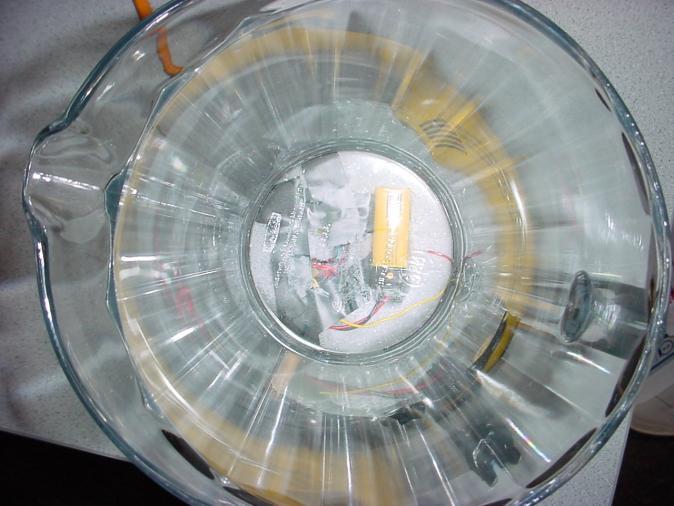
Photograph
1: The circuitry under the pitcher can be seen through the glass
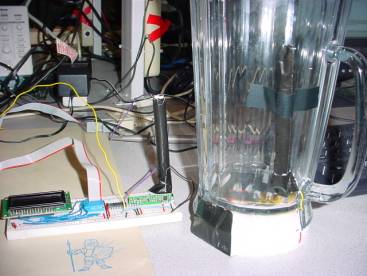
Photograph
2: Side view of the pitcher and foam
bottom.

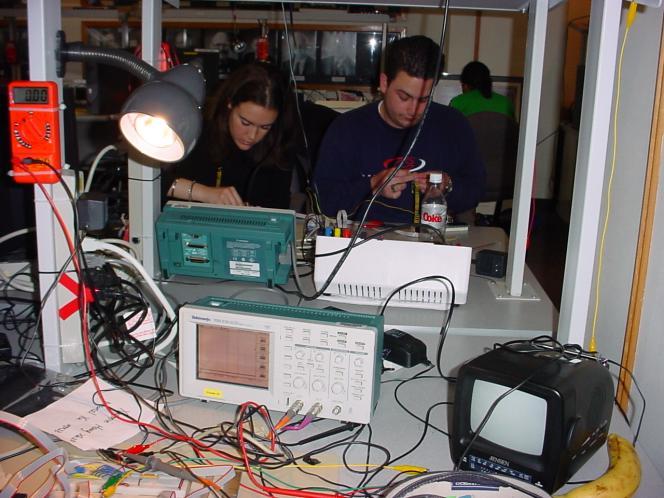
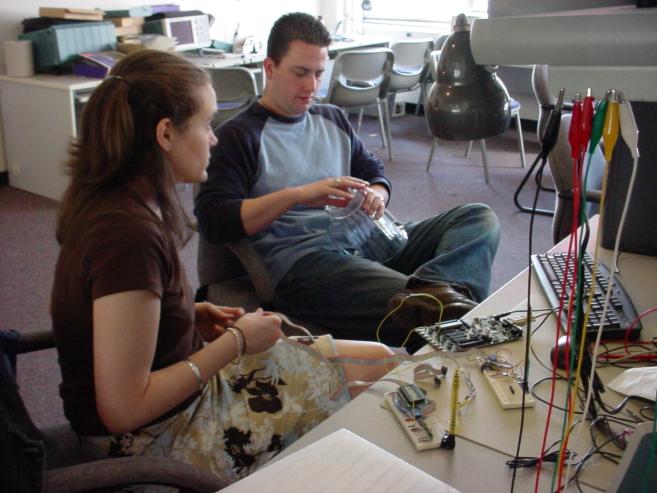
Photograph
3: Matt and Erin are hard at work!
Photograph
4: How to mount the accelerometer?
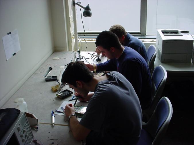
Photograph
5: Matt and Solder, watch out!
Appendix E
#include<Mega32.h>
#include<math.h> #include<stdlib.h>
#include<stdio.h> #define begin {#define end }#define ICP PIND.6 //input capture pin#define MAX 65535
#define LCDwidth 16 //characters
#define alpha .3 //for the low pass filter//button debounce states
#define noPush 1#define push 2#define maybePush 3#define maybeNoPush 4 //system states #define tableSet 1
#define monitor 2#define refill 3//state variables for debounce state machine
unsigned char incrButton;
unsigned char decrButton;
unsigned char incrFlag;
unsigned char decrFlag;
unsigned char buttonCounter;
unsigned char systemState;
#asm
.equ __lcd_port=0x15#endasm
#include<lcd.h> // LCD driver routines
char cycleFlag;
unsigned int t1;
unsigned int t2;
unsigned int time1;
unsigned int time2; float accelX;
int angle;
int maxAngle; char lcd_buffer[17]; // LCD display bufferchar i;
char tableNum;
char pitcherNum; void debounceButtons(void);
void monitorState(void);
void tableSetState(void);
void refillState(void);
//**********************************************************
//timer 0 compare ISR
interrupt [TIM0_COMP] void timer0_compare(void)
begin if(buttonCounter == 30) { debounceButtons(); buttonCounter = 0;}
else { buttonCounter++;}
end //**********************************************************
//timer 1 capture ISR
interrupt [TIM1_CAPT] void timer1_capture(void) begin if(ICP)begin //rising edge
t2 = ((unsigned int)ICR1L) | ((unsigned int)ICR1H)<<8; //saves the rising
edge time
TCCR1B = TCCR1B & 0xBF; //setting ICES1 in the TCCRIB - capture next time onfalling
TCNT1H = 0; TCNT1L = 0; if (t1 != 0) begin cycleFlag = 1; end end else begin //falling edge t1 = ((unsigned int)ICR1L) | ((unsigned int)ICR1H)<<8; //saves the falling edgetime
TCCR1B = TCCR1B | 0x40; //capture time on rising next endend //***********************************************************
//debounce statemachine for increment and decrement buttons
void debounceButtons() begin
switch (incrButton) begin case noPush: if (!PINA.1) incrButton = maybePush; break; case maybePush: if (!PINA.1) begin incrButton = push;incrFlag = 1;
end else incrButton = noPush; break; case push: if (PINA.1) incrButton = maybeNoPush; break; case maybeNoPush: if (PINA.1) begin incrButton = noPush;incrFlag = 0;
end else incrButton = push;break;
end
switch (decrButton) begin case noPush: if (!PINA.2) decrButton = maybePush; break; case maybePush: if (!PINA.2) begin decrButton = push;decrFlag = 1;
end else decrButton = noPush; break; case push:if (PINA.2)
decrButton = maybeNoPush; break; case maybeNoPush: if (PINA.2) begin decrButton = noPush;decrFlag = 0;
end else decrButton = push;break;
end end // void //**********************************************************
//method for when monitoring the angle of the pitcher
void monitorState() begin
//resets to table setif (PINA.0 == 0) begin
//set up timer 0TIMSK = 0x02; //need to be checked
OCR0 = 250; //set the compare reg to 250 time ticks
TCCR0=0b00001011; //prescalar to 64 and turn on clear-on-match
#asm ("sei");
lcd_clear(); maxAngle = 0; angle = 0; systemState = tableSet; end else if(cycleFlag == 1) begin cycleFlag = 0; time1 = t1; time2 = t2;
//calculate the acceleration
accelX = ((((float)time2) - ((float)time1))/((float)time2)-.47)/.125; if( -1 <= accelX && accelX <= 1 ) begin //calculate the angle angle = (int)(alpha*fabs( (asin(accelX) * (180.0/PI)) ) + (1-alpha) *((float)angle));
//display maximum angle thus far
if (angle >= maxAngle) begin maxAngle = angle; end //if (angle > oldAngle) //the display for monitor state
lcd_gotoxy(0, 0);
sprintf(lcd_buffer,"Table %d Round %d",tableNum, pitcherNum); lcd_puts(lcd_buffer);lcd_gotoxy(0,1);
sprintf(lcd_buffer,"BOOZE: ");//%d", maxAngle);
//the status bar code for(i = 0; i < 5; i++) begin lcd_buffer[7 + i] = 0xff; end if(maxAngle > 60)
lcd_buffer[11] = 0x4f; if(maxAngle > 65) lcd_buffer[10] = 0x4f; if(maxAngle > 72) lcd_buffer[9] = 0x4f; if(maxAngle > 75) lcd_buffer[8] = 0x4f;
lcd_puts(lcd_buffer);
//condition where glass is empty
if (maxAngle >= 80) begin //was angle until matt changed it
lcd_clear();systemState = refill;
end end //if( -1 <= accelX && accelX <= 1 )end // if(nFlag && notEmpty)
end //monitorState
//*************************************************************
// the state for selecting the table
void tableSetState(void)
{ if (PINA.3 == 0) begin TCCR1B = 0xC1;
TIMSK = 0x20; //need to be checked
#asm ("sei"); lcd_clear(); systemState = monitor; end else begin if ((incrFlag == 1) && (tableNum != 99)) begin incrFlag = 0; tableNum++;end
if ((decrFlag ==1) && (tableNum != 1)) begin
decrFlag = 0; tableNum--; end
pitcherNum = 1; sprintf(lcd_buffer,"Please Select"); lcd_gotoxy(0, 0); lcd_puts(lcd_buffer); sprintf(lcd_buffer,"Table Number: %d",tableNum); lcd_gotoxy(0, 1); lcd_puts(lcd_buffer); end} //*********************************************************
// state to notify need for refill
void refillState(void)
{ //resets to table setif (PINA.0 == 0) begin
//set up timer 0TIMSK = 0x02; //need to be checked
OCR0 = 250; //set the compare reg to 250 time ticks
TCCR0=0b00001011; //prescalar to 64 and turn on clear-on-match
#asm ("sei");
lcd_clear(); systemState = tableSet;end
//resets to monitorelse if (PINA.3 == 0) begin //resets to table set
lcd_clear(); systemState = monitor; pitcherNum++; end else begin sprintf(lcd_buffer,"Table %d Round %d",tableNum, pitcherNum); lcd_gotoxy(0, 0); lcd_puts(lcd_buffer); sprintf(lcd_buffer,"REFILL"); lcd_gotoxy(0, 1); lcd_puts(lcd_buffer); maxAngle = 0; angle = 0;end
}
//*************************************************************
//contains initialization and the system statemachine
void main(void)
{ //refill will be set to 0 initially //when the angle reaches 85 degrees the refill signal will be set and thewaitstaff will be alterted
//after it is set to 1 print message and then set back to 0lcd_init(LCDwidth); //initialize the display
//set up timer 0TIMSK = 0x02; //need to be checked
OCR0 = 250; //set the compare re to 250 time ticks
TCCR0=0b00001011; //prescalar to 64 and turn on clear-on-match
DDRB = 0xff; DDRA = 0x00; PORTB = 0x00; t1 = 0; //should we really be setting the t1 and t2 to 0
t2 = 0; cycleFlag = 0; time1 = 0; time2 = 0; angle = 0; maxAngle = 0; tableNum = 1;pitcherNum = 1;
systemState = tableSet;
//initialize buttons decrButton = noPush;incrButton = noPush;
incrFlag = 0; decrFlag = 0; buttonCounter =0 ; #asm ("sei"); //system statemachinewhile(1) begin
if (systemState == monitor) begin monitorState();end
else if(systemState == tableSet) begin
tableSetState();end
else if(systemState == refill) begin refillState();end
end // while(1)end //main()
References
Analog Devices Accelerometer ADXL202E
http://www.analog.com/UploadedFiles/Data_Sheets/567227477ADXL202E_a.pdf
Radiotronix Receiver RCR-433-RP
http://www.radiotronix.com/products/prodrcrrp.asp
Radiotronix Transmitter RCT-433-AS
http://www.radiotronix.com/products/prodrctas.asp
FCC frequency regulations
http://www.ntia.doc.gov/osmhome/allochrt.pdf
LCD data sheet RCM2034R
http://instruct1.cit.cornell.edu/courses/ee476/labs/s1999/rcm2034r.pdf