Cornell University
Paint Program with Mouse Control
Steven Keiper and Ragavan Mahedevan
Introduction
High Level Design
GoalsProgram/Hardware Design
General Design and Hardware/Software Tradeoffs
Relevant Standards
Existing Patents/Copyrights/Trademarks
Program DetailsResults
Hardware Details
Things We Tried That Did Not Work
Speed of Execution/ AccuracyConclusion
Safety/Interference
Usability
Meeting ExpectationsAppendix
Conforming to Standards
Intellectual Property Considerations
Ethical Considerations
Program Listing
Schematics
Cost Details
Specific Tasks
References
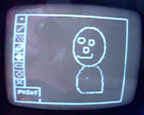
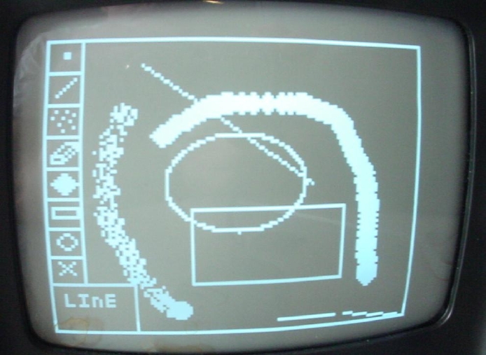
For our final project, we implemented a drawing program similar to Microsoft Paint using a PS/2 mouse to draw onto a TV screen.
Microsoft Paint is a drawing program that allows the user to create color images by using an assortment of painting tools like the pencil tool, the line tool, the rectangle tool, and the oval tool. The program is relatively simple, yet very useful as well. This made it ideal for a project such as this. We got the idea after looking at various past final projects that implemented basic drawing pads using various other input devices. We decided to expand upon these projects, by implementing additional tools and using a PS/2 mouse as the input device. In the end, the user should be able to easily create complex images on the TV screen through a user-friendly interface.
Our initial goal was to be able to draw and erase images on a black and white TV screen by using the mouse like the pencil tool in Paint. After this goal was completed, we hoped add more tool options, starting with the line tool, moving onto the shape tools like the rectangle and oval tools, and finally finishing up with paint and fill tools. Another potential goal was to implement a more advanced display like gray-scale or color.
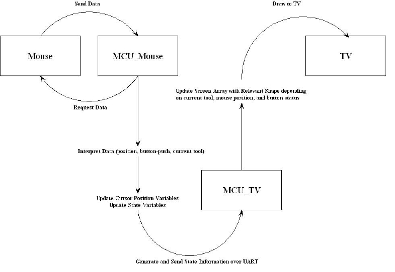
After looking at the TV Minesweeper project that previously dealt with video generation interfaced with a PS/2 mouse, we discovered that a single microcontroller would probably not be sufficient to implement our project. The reason for this is that there is not enough time to read all the data from the mouse in the single line interval between each sync pulse generation interrupt. Instead, we would need 2 microcontrollers, one to handle the TV video generation and another to deal with the mouse and the paint program. We could then use the TV microcontroller to send and receive commands to and from the mouse microcontroller via UART communication. An added advantage of this setup is that it enabled us to break up the project into 2 separate main tasks with separate speed and memory considerations. This greatly simplified the programming and debugging process since we were able to better pinpoint the area of concern.
A high-level block diagram of our design is shown below:
The two main standards that are relevant to our project are the PS/2 Mouse Protocol developed by IBM and the National Television System Committee (NTSC) video standard for the TV. The PS/2 Mouse Protocol specifies the physical PS/2 port as a 6-pin mini-DIN, with Pin 1 carrying the mouse data, Pin 3 to ground, Pin 4 to 5V DC Power, and Pin 5 carrying the mouse clock. A pinout of the PS/2 mouse port, from Adam Chapweske’s page on the PS/2 mouse, is shown below:Existing Patents/Copyrights/Trademarks
The mouse uses a serial protocol to transmit the data, starting with a start bit, followed by 8 data bits, followed by a parity bit, and finally a stop bit. In the remote mode of operation, the mouse sends its movement and button information using three bytes every time the host microcontroller requests data. For this project, we used an adaptation of the NTSC standard that we also used in Lab 4.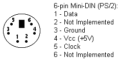
Figure 2: PS/2 Mouse Pinout (from Chapweske)
There are a number of various paint programs (such as Microsoft Paint) which are well-known for accomplishing similar functions as our design. We do not feel we have infringed upon any existing copyrights or patents since our design is very simple and has limited commercial applications. As a result, there is no potential for receiving a patent for our design.
We split up the code between our 2 different microcontrollers. One, mcu_mouse.c, received information from the mouse and sent information about the status of the mouse to the TV and the other, mcu_tv.c, generated the TV signal and contained the code that allowed the user to draw various shapes. For the mcu_mouse.c code, we used the basic mouse communication functions (mouse_send, mouse_read, poll_mouse, and reset_mouse) that were developed by Chee Ming, Chaw and Elaine Siu for their Minesweeper Project for this course last year. For the mcu_tv.c code, we used Professor Land’s code from Lab 4 as the basis for our own code.
In the mouse code, we would handle the selection of tools from the left hand side of the screen and limit the mouse to the portion of the screen the user was allowed to draw to. We would not notify the TV of a mouse click if the user was selecting a new tool. By doing this, we prevented the tool menu from being part of the drawable screen while allowing the TV to know that a new tool had been selected.
At a regular interval, scheduled by timer 1, we polled the mouse for information and updated the state variables related to the cursor position and button state. We then sent this mouse information to the TV MCU. The information sent by Mouse MCU to the TV MCU is shown in the diagram below:
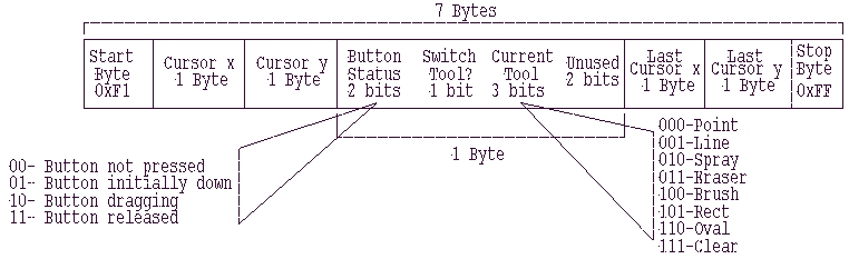
Figure 3: Information sent over UART from Mouse MCU to TV MCUThe information includes the cursor position, button status, and current tool. This information is sent through UART communication at 57600 bps.
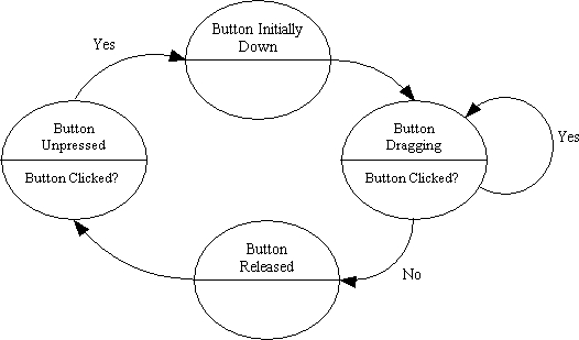
The mouse button could be in one of four different states: button not pressed, button initially down, button dragging, and button released. Given information about whether the button was down or up and the state of the mouse the last time it was polled, we determined the current state of the mouse button that would then be sent to the TV. The button initially down state would occur once per mouse click and would only last for the instant at which the user clicked the mouse button. The button dragging state would exist while the mouse button was being held down and the mouse was being moved around the screen. The button released state would occur once per mouse click after the user released the button. A state transition diagram of our mouse button states is shown below:
The TV MCU receives information from the Mouse MCU at a regular intervals and then processes this information. Depending on the button state and current tool, the TV MCU would then store relevant information or draw what needed to be drawn to the screen. If in the button initially down state, the TV MCU stores the cursor position into a variable called click_origin which would be used as the initial point for the line or the initial point representing the bounding box of the rectangle or oval. In the button dragging state, the pixels in the screen array are permanently updated if the current tool is the point tool, spray tool, brush tool, or erase tool. In the case of the line, rectangle, or oval tools, we would draw a wire frame or set of points representing the final shape so that the user could preview what the final image would look like before printing something to the screen. For these 3 tools, we used the invert option in the drawing routines so that we could draw a line and then invert at the next frame in order to easily erase it without affecting the permanent image that would be displayed on the screen. In the button released state, the line, rectangle, or oval would be drawn permanently to the screen with paint. In this state, the cursor location would be used to determine the second point of the line or bounding box for the oval or rectangle.
To draw the ovals, we used arrays of sine and cosine values stored in flash which could then be used to accurately draw a circle. During the final painting of the circle in the button released state, we had to disable the screen refresh because the calculation was intensive and took a long time to draw to the screen buffer. For our spray paint tool, we created 8 frames of bitmaps containing randomly-generated pixels which would be drawn to the screen buffer at the cursor location.
One of the most challenging problems that we ran into was how to draw a pixel at the cursor location without affecting the permanent image that would be drawn to the screen. During each screen buffer refresh we would store the color of the cursor location and then invert that pixel to show where the cursor was. Additionally, we needed to set the pixel at the last cursor location to what it was before the mouse was moved there. The situation became more complicated if that pixel was drawn to with permanent paint. We had to use information about the color of the pixel in order to overcome this.
In order to fully implement our design, we needed to add 2 additional functions, put_icon and put_spray. Put_icon would draw a bitmap with an opaque mask which would overwrite all the pixels in the area of the bitmap with the bitmap image. Put_spray would draw an icon from a bitmap but would only draw specific pixels if they were a 1 and would leave other pixels untouched.
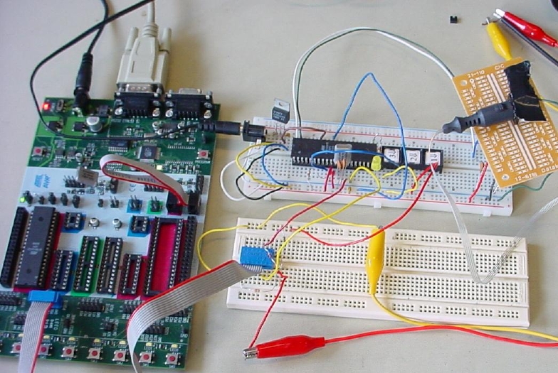
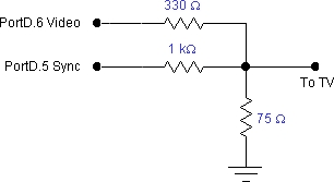
Things We Tried That Did Not WorkFigure 5: A picture of our CircuitWe used the microcontroller on the STK500 board in order to control our TV and placed our second microcontroller on a separate breadboard that dealt with the mouse. The circuit for the TV generation is identical to the one that was used in Lab 4, using pins 5 and 6 of Port D to output to the TV. We set up the prototype board for our second microcontroller as described in class. We had some difficulty in building this board, running into problems due primarily to unreliable connections between our hardware and board. After a couple attempts at re-building the board, we were finally able to get it relatively stable. We produced our 5V power supply from a 12V supply by using an LM340 5V regulator, a diode, some capacitors, and a power socket. We put in a reset button in order to reset the microcontroller. We also connected a heartbeat LED to Port C. The two microcontrollers were connected through the UART communication, pins 0 and 1 of Port D. An overall hardware schematic of our design is shown in the Appendix section, Schematics.
The PS/2 mouse has 4 usable signals: the data, the clock, Vcc, and Ground. The pinout for the PS/2 mouse port is given in the Relevant Standards section of our High Level Design. We connected the data and clock pins to pins 0 and 1 of Port A, respectively. Since it would be difficult and unreliable to solder wires directly onto the PS/2 plug itself, we bought a receptacle that would connect to the PS/2 plug and whose output pins could be soldered onto a board for easy access. We had to add a small capacitor to the clock line coming from the mouse in order to make the mouse function reliably.
One major tool that we would have liked to have implemented was a fill (paint bucket) tool. This tool would fill an area with white paint given boundaries represented by white paint surrounding that area. This would have been very complicated to implement because it typically involves a recursive algorithm that recursively evaluates the color of its neighbor pixels in order to determine how far the fill should spread. This algorithm would have very easily and quickly overflowed the stack on the TV MCU. We developed a way in which this could have been theoretically implemented on the Mouse MCU although it was still complicated and would have taken a lot of time to get working correctly.
To implement this, we would have had a buffer on the mouse that could store half of the screen from the TV. When the user would click the fill tool on an area, depending on the cursor location, either the top or bottom half of the screen buffer would be sent over the UART and placed in the mouse’s buffer. The recursive algorithm would then be called on this “half-screen buffer” and this half of the screen buffer would be filled according to the arrangement of pixels bounding the fill area. We also would have had to store an array of boundary pixels (width of the screen). Each time the recursive algorithm would run into the half-screen boundary, the corresponding pixel would be set. After completion of the recursive algorithm, the buffer on the mouse would be sent back to the TV and dumped on the screen buffer. This algorithm would be repeated with alternating halves of the screen until none of the pixels in the boundary array were set. We think we would have been able to implement this if we had more time, but unfortunately due to hardware issues in the beginning, we were unable to implement this.
Our design appears to work flawlessly, interacting with the user promptly and producing the desired images on the TV screen accurately and quickly.Speed of Execution/ Accuracy
There is very little delay between the movement of the mouse and the corresponding movement of cursor image on the screen. This helps the user in establishing direct control over the drawing process, resulting in more precise images. When we first began testing our design, we had some trouble with stray points occasionally being drawn to the screen, but in the end, we were able to fix our design so that the images produced on the screen are precise, with no noticeable flicker or artifacts. When drawing circles, we have to stop interrupts in order to create a similarly precise image.Safety/Interference
There are no significant safety considerations with this project. There is no risk of causing seizures due to flickering graphics as in certain video games and television programs. Our design should not cause any interference with other projects. The CPU noise generated by our design should be minimal and we are not dealing with RF signals or any wireless signals that might interfere with other projects.Usability
The simple one-button mouse interface makes the design easily operable by anyone who can use a computer mouse. In order to create a free-form drawing, all the user has to do is hold down the mouse button and move the mouse around. To select the other tools, the user simply has to click on the corresponding icon in the menu on the left side of the screen. A simple one-word description of the selected tool is provided at the bottom of the menu so that a new user won’t have to waste time testing the tool to figure out what it does. As part of the testing process, we let classmates use our paint program without any prior instructions and all of them were able to figure out how to use it immediately.
Once selected, the paintbrush and spray tools are used in an identical manner as the free-form point tool while the line, oval, and rectangle tools are used by clicking the mouse button to set the starting point of the shape and then dragging the mouse in order to get the desired size before releasing the mouse button to form the final image. When creating these shapes, the screen shows a real-time preview of the current image as the user expands and contracts the shape to the desired size. This helps the user visualize what he or she is drawing before committing it to the screen.
In the end, our design met and eventually exceeded our expectations. We were able to achieve our initial goal and then go on to implement almost all of our more advanced goals. The only tool that we did not implement was the fill tool, although we were able to come up with a good algorithm for potentially doing so. If we had more time to experiment with the implementation of this tool, we feel as though we would have gotten it to work. We also did not have the time to implement a more advanced color display.
The major roadblock in our design process was the creation of the prototype board for our second MCU. We spent a lot of time on this, even creating a brand new prototype board on a large solder board, before we came to the realization that the problem was due to a bad connection between the MCU and 40-pin connector. After simply getting a better, different kind of connector, we were able to get our original prototype board to operate correctly.
If we had the chance to do this again, we would hopefully be able to get past the step of building the prototype board relatively quickly, giving us ample time to implement the fill tool. We might also have the time to implement a grayscale display.
Our design properly deals with the PS/2 Mouse Protocol and the NTSC video standard. We were able to correctly communicate with the mouse, getting the information that we needed from it. The design also follows the NTSC standard, generating the correct video signal as evidenced by the correct display on the screen.
As discussed in the High Level Design section, even though this project bears some superficial similarity to Microsoft Paint, there should be no real problems with intellectual property. We used some code from the Minesweeper project from last year, but we have properly cited their contributions in our code as well as here in the report. We also used code provided by Professor Land for video generation. There do not appear to be any patent opportunities for this project.
1. To accept responsibility in making engineering decisions consistent with the safety, health and welfare of the public, and to disclose promptly factors that might endanger the public or the environment.
We have honestly considered all cases in which the public might possibly be harmed by our design and have tried to eliminate all such cases.
3. To be honest and realistic in stating claims or estimates based on available data.
All of the claims made in this report are honest and realistic, based on the observable results and our best estimates.
6. To maintain and improve our technical competence and to undertake technological tasks for others only if qualified by training or experience, or after full disclosure of pertinent limitations.
We have used this project to improve our technical competence by exploring the ways in which we can use our technical knowledge of microcontrollers in order to develop useful projects such as this.
7. To seek, accept, and offer honest criticism of technical work, to acknowledge and correct errors, and to credit properly the contributions of others.
We have tried to get help from the TAs and Professor Land whenever we felt it was needed, seriously considering their suggestions and criticisms. We have also taken care to credit the contributions of others to this project.
9. To avoid injuring others, their property, reputation, or employment by false or malicious action.
We made sure to consider our fellow classmates by taking care not to disturb or damage their work and giving them the appropriate room they needed to work.
TV Microcontroller code: mcu_tv.c
Mouse Microcontroller code: mcu_mouse.c

- 1 PS/2 mouse ($1.75)
- 1 PS/2 receptacle to connect mouse port to our hardware (1 x $0.75)
- 1 small solder board (1 x $0.80)
- 1 TV with cable (free from lab)
- 2 Atmel Mega32 microcontrollers (2 x $8.00)
- 1 STK-500 board (free from lab)
- 1 white boards (1 x $5.00)
- Resistors, capacitors, LEDs, wires (free from lab)
- TOTAL COST = $24.30
We worked together on most of the tasks, rather than split up the tasks between us. The main tasks carried out in this project were:
- Creating the code for the mouse
- Creating the code for the TV
- Building the Hardware
- Testing
- Writing the Report and converting it to HTML
Adam Chapweske’s General PS/2Mouse/Keyboard Protocol
http://panda.cs.ndsu.nodak.edu/%7Eachapwes/PICmicro/PS2/ps2.htm
Adam Chapweske’s PS/2 Mouse Interface (More specific)
http://panda.cs.ndsu.nodak.edu/%7Eachapwes/PICmicro/mouse/mouse.html
IEEE Code of Ethics
http://www.ieeeusa.org/documents/CAREER/CAREER_LIBRARY/ethics.html
Amtel Mega 32 Datasheet
http://instruct1.cit.cornell.edu/courses/ee476/AtmelStuff/full32.pdf
Minesweeper Project (Chee Ming, Chaw and Elaine Siu)
http://instruct1.cit.cornell.edu/courses/ee476/FinalProjects/s2003/cc358/ECE476/index.htm
Professor Land’s Video Generation Code
http://instruct1.cit.cornell.edu/courses/ee476/video/Video32v3.c