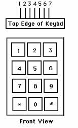
SmartBlinds

Hardware Design


Our SmartBlind system consists of multiple hardware systems. We constructed all of our circuit hardware on two proto-boards: one houses the keypad and LCD, and the other contains the light sensor, motor/H-Bridge, and Hall effect sensor circuits.

The keypad is used to take user input for the switching of modes, the entering of times, and the manual adjusting of blind tilt in UPDOWN mode. The keypad pictured below is the keypad we used for our SmartBlind system. Each pin corresponds to a certain row or column, and these pins are fed into port B on the Mega32. To read a button press, the most significant four bits of the port are set to input with pull-ups while the least significant four bits are set to outputs. A button press then connects one of the column pins to one of the row pins, bringing one of the inputs to zero. As a result, all of the row pins are high except for one, while the column pins are all zero. This value is stored in a variable called key. After a five-us delay, the four most significant port pins are set to outputs, and the four least significant pins are set inputs with pull-ups. The same button is still being pressed since a user cannot press and release a button in less than five microseconds. Now the connection drives one of the column pins low, and we then know which column the button press corresponds to. This value is ORed into the key variable, and this final value represents which key was pressed. (See the keypad diagram and pinout below.)


Pin 1 -- col 1 4 7 *
Pin 2 -- col 2 5 8 0
Pin 3 -- col 3 6 9 #


Pin 4 -- row 1 2 3
Pin 5 -- row 4 5 6
Pin 6 -- row 7 8 9
Pin 7 -- row * 0 #

The following is a close up of the LCD and keypad that we used:


The 16x4 LCD is used to display the mode of operation (TIMESET, OPTIMIZE, PRIVACY, ALARM, or UPDOWN). It also displays the current time as well as mode-specific data. The TIMESET and ALARM modes have a field to show the time as it is being entered, and the OPTIMIZE mode shows the light values (ranging from 0 to 1) for each of the three LEDs. These values are reprinted about every second so the LCD always shows the current light values in OPTIMIZE mode.

For OPTIMIZE mode, we detect the light in the room on three green LEDs. Green LEDs, according to Prof. Land, have the best response to human visible light (since humans are most sensitive to green). Since a LED registers a voltage across its terminals when exposed to light in the direction of its bulb, we position these LEDs in different directions to get a feel for which direction the light is coming from. The output of the LEDs is then fed into an operational amplifier circuit with a low-pass filter that has a gain of five to amplify the signal before passing it to the analog-to-digital converter (ADC). The low-pass filter uses a 1uF capacitor and a 200KOhm resistor to get an RC time constant of 0.2s. Therefore, the noise is filtered out, but the signal also stabilizes quickly. Below is a circuit diagram that shows the construction of the LED/op-amp circuit. Three such circuits were used for the three LEDs in our project. Each output went to a different input (0,1,2) of port A into channel 0-2 of the ADC.


When we want to position the blinds in a different position, we use a 6V DC geared motor to turn the blind-adjustment shaft. The motor is driven by an H-Bridge that is in turn driven by two pins of port D. These two pins would be low-high to move the motor in one direction and high-low to move the motor in the other direction. Below is a diagram showing the H-Bridge and motor circuit. When D.0 = 5V and D.1 = 0V, the npn Q4 transistor is on and the pnp Q2 transistor is on while the other two transistors are off. This makes the motor spin backwards. When D.0 = 0V and D.1 = 1V, the pnp Q1 transistor is on and the npn Q3 transistor is on, while the other two transistors are off. This time, the motor spins forwards. D.0 and D.1 are both zero when we want the motor to stop, and both pins are never high at the same time; however, if such a state should occur, it would also turn the motor off. We used a seperate 6 Volt power supply for both the H-bridge and the motor.


The Hall effect sensor outputs a five-Volt signal normally and a zero-Volt signal when a magnet is close to it. The sensor is used to help determine how many times to turn the shaft at any given time. The Hall effect sensor, attached near the shaft of the motor, registers a zero-Volt pulse when a magnet on the shaft passes by it. This pulse shows when the motor shaft makes one full revolution. This value is also passed into the ADC.


You can see a close up of our motor and H-bridge here as well as the tilted green LEDs tilted at different angles at the bottom of the picture: