Hardware:
The hardware components of our project included the 9 character placer, the 4 button selector, the Nintendo Duck Hunt gun, a custom PC board, and a custom breadboard.
The 9 character placer is basically a set of 9 push-button switches from RadioShack. Each switch had two metal contacts- we connected one contact to ground, and the other contact to a port pin. Since the controller would be moving around, a solid contact was achieved not by soldering, but by twisting wires around the contact tightly.
The 4 button selector is a row of 4 pushbuttons. There are 5 pins. The rightmost pin is ground, and the other pins correspond to the buttons. The rightmost pin was connected to ground, and the other pins were connected to their respective port pins.
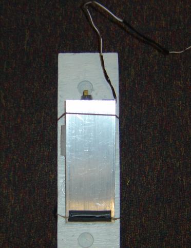
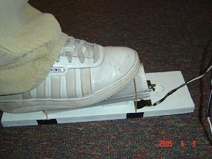
The foot-pedal was made by using a rectangular piece of metal- top of pedal, and a rectangular piece of wood- bottom of pedal, that we obtained from the Rhodes Machine Shop. A sponge was placed between the top and bottom of the pedal to act as a spring. A pretty durable pushbutton switch was placed between the top and bottom of the pedal, and would be pushed down whenever the player stepped down on it. Rubber bands were used to secure the pedal in place instead of using hinges.
The video signal that connected the Atmel Mega32 to the TV is identical to the one from lab 4 of ECE 476. It is basically a digital to analog converter that produces a video signal where the resistors can alter the voltage levels (0V = sync level, 0.3V= black level, 1.0V = white level) of the signal from the PORTD pins. The circuit is reproduced below:
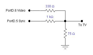
More information can be found here.
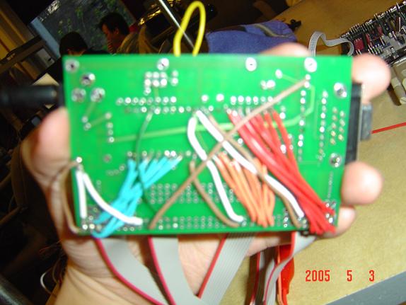
Our custom PC board was made following the instructions from the Microcontroller Board link on the course website. However, we needed more than 2 ports, so we soldered extra ports onto the board. Also, because there were no more reset buttons, we simply soldered a wire that could short the two vias next to the programming header. We needed a lot of port pins, so there were a lot of wires underneath our pc board.
The Nintendo Duck Hunt gun was decoded' with the help of the pin-out diagram provided by the DuckHunter Video game from last year's final projects website. We also used the oscilloscope to double check if our gun worked the same way, and to see how the gun sampled. The diagram of the gun pin-outs is re-drawn by us below:
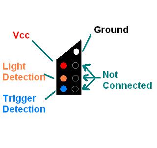
In order to obtain the correct signal from the gun, the following circuits also had to be built:
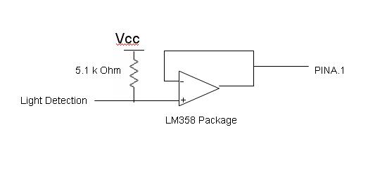
Light Detection Circuit:
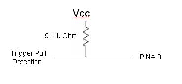
Trigger Pull Circuit:
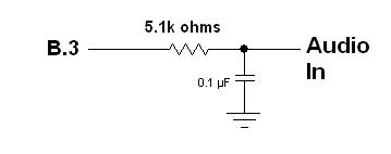
The sound circuit simply consisted of an output from a port pin, and this signal passed through a low pass filter circuit with a 0.1µF capacitor and a 5.1k Ohm resistor, which was then linked to the audio input of the TV.
With all this hardware, there were a lot of wires, and debugging or figuring out which wire went where would be very difficult. To solve this problem, we labeled all the wires and bus-ed' the wires by taping them together.
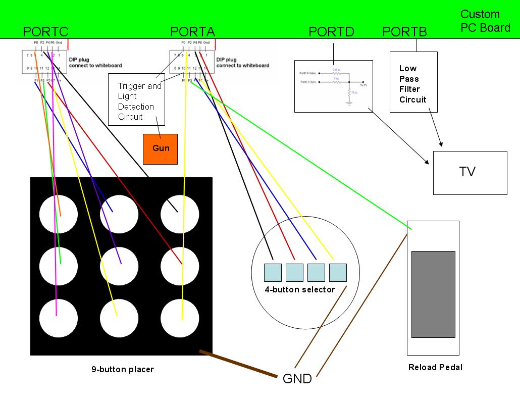
The following is a diagram showing how all the hardware was wired up: