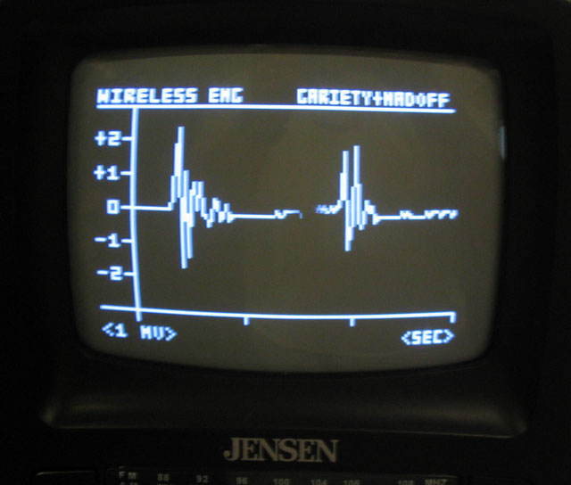
ECE 476 Final Project: Wireless Electromyograph

Arthur Gariety (ajg47) and Benjamin Madoff (bsm24)

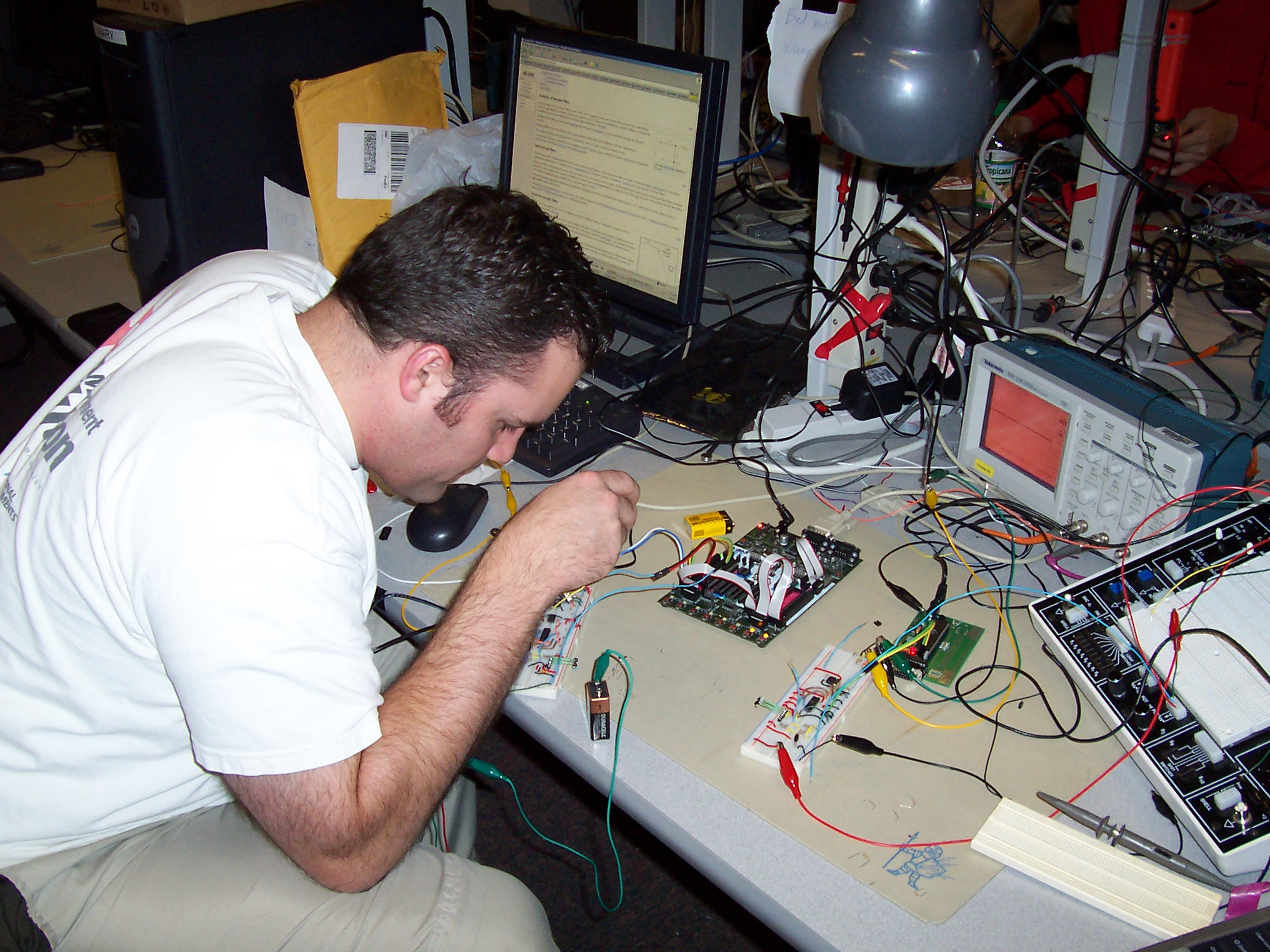
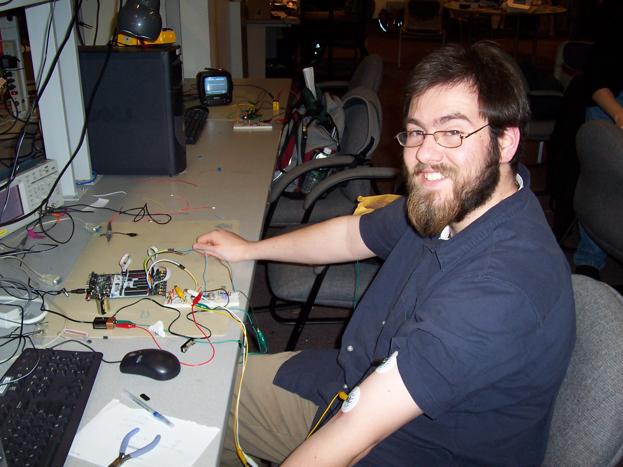
Arthur Gariety, from Sandia National Labs doing his M.ENG here at Cornell, testing the circuit Ben Madoff, junior electrical engineering major, biomedical engineering minor, hooked up to the EMG


Disclaimer: this is a student project, NOT a medical device.


Introduction


High Level Design


Program / Hardware Design


Results of the Design


Conclusion


Appendices


Introduction


This project implements a wireless surface electromyograph that displays the signal using a television as an oscilloscope.

Electromyography detects the electrical signals that the human body generates to contract muscles. Detecting very low voltages in the milliVolt range on the skin surface is not a trivial task. As shown in figure 1, EMG signals are inherently low frequency signals. The human body is a great antenna and filtering out RF and 60Hz power system noise is essential to observing the EMG signal. The course safety requirement for the final projects required that any human body connection be electrically isolated from the 120V power grid. Thus, the human side of the system must be powered using 9V batteries. Converting the analog EMG signal to digital and transmitting using a wireless transmission protocol was an effective way to electrically isolate the human. The transmitted EMG data was displayed on a television we setup to be a virtual oscilloscope.

Figure 1: Example EMG waveforms taken from different parts of a muscle, from C. J. De Luca, 1997, "The use of surface electromyography in biomechanics", Journal of Applied Biomechanics, 13 (2): 135-163.


High Level Design


The study of these electrical signals contractions is an important research tool when studying animal and human biology. We chose this project because it was an interesting way to combine our knowledge from a variety of fields to build a complex machine. We used what we learned in this class about microcontrollers to build an analog to digital converter and generate a TV display. We used our knowledge of analog circuitry to build the infrared transmission. Finally, we learned about nerve conduction across muscles to build an amplifier capable of detecting nerve impulses while filtering out noise.

In order to implement a wireless EMG, four major components are required. First an instrumentation circuit is required to receive, filter, bias, and amplify the signal so that it can be converted to a form suitable to be digitally sampled using 8-bit, 0-5v analog to digital conversion. The second component is the transmission circuit. This circuit performs the analog to digital conversion, transmits the signal in RS-232 format, translates the RS-232 format to the IrDA standard, and transmits the wireless infrared signal. The third component is the receive circuit which receives the IrDA standard signal and converts it back to RS-232. The fourth component is the display circuit. A microcontroller is used to receive the RS-232 signal and drive a television with the necessary NTSC compatible signals that display the EMG signal digitally on the TV as a digital oscilloscope (figure 2).

Figure 2: Wireless EMG in four steps


To implement this design, four components were used: a front end EMG amplifier, encoder, and transceiver (figure 3), an STK500 (figure 4), a back end transceiver and decoder (figure5), and a Mega32 prototype board (figure 5). The front end amplifier is a differential amplifier (INA106, see appendix) that amplifies the voltage drop between the two skin adhesive electrodes the human is wearing (generally on the bicep). This signal is sent to the analog to digital converter (ADC) of the STK500 to be converted into an RS-232 signal and sent back out using the UART. The RS-232 signal is then encoded by the MCP2120 IR encoder and sent to the IR transceiver. The IR transceiver on the back end breadboard receives the signal and sends it to the MCP2120 for the data to be decoded into RS-232 data. The prototype board receives the RS-232 data and outputs it to the TV.
Figure 3: Front end EMG amplifier, encoder, and transceiver
Figure 4: STK500 to run the ADC and conversion to RS-232 data
Figure 5: Back end transceiver and decoder with protoboard
This figure sums up the circuit. Notice, no wires connect the left half to the right half.


There were opportunities to trade software for hardware. The gain of the differential amplifier was set by the resistors in the INA106 precision gain differential amplifier packaging (see appendix) and external resistors. Using the hardware gain, a small amplitude signal appears on the TV/oscilloscope. The hardware gain could be increased only so far, because it became difficult to match the resistors used to set the gain. Instead of trying to increase the hardware gain more, we chose instead to add a variable software gain. By pressing a button, a gain of 1, 2, 4, or 8 can be selected by left shifting the amplitude of the signal displayed on the TV. Another tradeoff was the choice to use the MCP2120 Infrared Encoder/Decoder (see appendix) to encode the signals before they were transmitted and decode them when they were received. It was possible to use the Atmel Mega32 to encode and decode the signals, but since the Mega32 on the decode side was running the TV display code, this option had to be discarded.

Three standards were used in this project: RS-232, IrDA, and NTSC. RS-232 is the standard for serial communication. It was used to communicate between the Mega32 chips and the infrared (IR) encoder/decoders. IrDA stands for the Infrared Data Association and is the standard for short range communication using infrared light. It was used to communicate between the two IR transceivers and between the IR transceivers and the IR encoder/decoders. NTSC stands for the National Television Systems Committee who defined the standard for monochrome television display.

Since one of the lab partners is an MEng student, Cornell University owns all copyrights and potential, patents related to this project. Since the ideas and implementation of our project hardware are solely our own there should not be any trademark, patent, or copyright infringement issues.

Program / Hardware Design


There are two Mega32s running different code in this project. The basic code was fairly simple: the first Mega32 runs ADC code studied in the digital thermometer lab, while the second Mega32 runs the TV code studied in the video game lab. There was a problem in that the STK500 Mega32 only communicates the ADC data. Several inputs were considered for the STK500, but integrating data in addition to ADC data was not feasible in the amount of time for the project. The prototype board Mega32 has two inputs, one freezes the data on the screen, the other performs a shift operation on the EMG signal before displaying it, creating a software gain. This was difficult to write because the Mega32 was close to its memory limit. Several unused functions were deleted and some of the variables were recast to keep memory use down.

Figure 6: The differential amplifier circuitry. The leftmost chip is the MAX666CPA voltage regulator which converts the 9V battery input into a 5V output used for Vcc for the breadboard. The middle chip is the LM7111 operational amplifier which creates a virtual ground at Vcc/2. The rightmost chip is the INA106 precision gain differential amplifier


The circuitry for the EMG measurement, above, needed to be electrically isolated from the 120V ground for the building for safety reasons. A 9V battery was used to charge the amplifier circuitry. The STK500, where the analog to digital conversion takes place, uses a Vcc of 5V, so instead of powering the amplifier with 9V, we used the MAX666CPA (see appendix) voltage regulator to create a Vcc for the whole breadboard of 5V.

The LM7111 operational amplifier was used to provide a virtual ground for the differential amplifier. Since the EMG signals are positive and negative, the amplifier needed to have positive and negative rails. Thus, the virtual ground was set at 2.5V. The differential amplifier used the 0V ground as -2.5V and the 5V Vcc as 2.5V. Since the STK500 and the breadboard share the same 0V ground, the signal coming in to the ADC would be an EMG signal with a 2.5V positive offset. The virtual ground was created by using a voltage divider to split 5V in half and apply it to the non-inverting terminal of the LM7111. The output was fed back to the inverting terminal of the op amp, creating a buffer, or voltage follower. In this way a stable reference voltage was created without loading the battery except through the voltage divider.

The front end amplifier was designed to amplify the potential across two points on a human muscle group. These potentials are fairly weak, since human nerve impulses travel at a variable depth beneath the skin surface. The signals are also strongest at 50Hz, which is close to the 60Hz noise that comes from the AC devices in the room. The first problem was solved by amplifying the signal as much as possible. The INA106 differential amplifier has a gain of 10, but that can be increased using external resistors. These resistors need to be closely matched, or there will be no output. We used 1MO external resistors, making the gain equal to:

The other problem, the 60Hz noise, was solved by using the differential amplifier to measure the signal. The signal from the proximal electrode m1, is subtracted from the signal from the distal electrode, m2. Since both signals travel the same path to the differential amplifier, it can be assumed that they pick up approximately the same amount of noise, n. The differential amplifier amplifies the difference of these two signals: A((m2 + n) - (m1 + n)) = A(m2 - m1), so the noise is canceled out. In choosing a differential amplifier to use for this project, we looked for one with a gain greater than 1, but we also looked for one with a high common mode rejection ratio (CMRR). The CMRR of a differential amplifier measures its ability to reject noise on the input. Using an amplifier with a low CMRR will produce more noise on the output, but an amplifier with a very high CMRR will also produce more noise on the output because the noise is not likely to arrive in phase, given the measurement tools we are using. The INA106 has a CMRR of 86db. We looked at differential amplifiers with a CMRR between 70db and 100db.

The electrodes for the experiment were connected the same way every time. Two skin adhesive electrodes were connected to Ben's left bicep. The inverting input of the differential amplifier was connected to the center of the left bicep. The non-inverting input was connected to the distal end of the left bicep. A third electrode was connected to the right elbow. This electrode was used as a reference electrode, and was connected to the virtual ground created by the LM7111. The reference electrode can be placed in any electrically neutral place on the body.

Figure 7: IR transmission circuit


The infrared transmitter circuit, above, was designed to convert the analog signal coming from the differential amplifier to digital and transmit it wirelessly to a receiver. The final digital signal is then output as a standard RS-232 UART signal on pin D.0 of the Mega32. A Microchip MCP2120 IrDA encoder/decoder is then used to convert the RS-232 signal to the IrDA standard. It is essential that the baud rates of the Mega32 UART and the IrDA encoder match. A clock oscillator circuit is used to drive the MCP2120 at 3.575945 MHz. The selection of this clock frequency was due to the fact that we scavenged these parts for free from previous ECE476 projects. Setting the BAUD 0:2 pins to 000 sets the MCP2120 clock divider value to 768. This produces a baud setting of:


The MCU must also be set to transmit at a 4661 baud rate to match the IrDA circuits. This is done by setting the UBRRL register to the correct value according to the equation:


It is worthwhile to note that a clock rate of 3.6864MHz would produce baud rates that are multiples of standard communication frequencies such as:


The IrDA compatible signal is then transmitted using a Zirlog ZHX1010 IrDA Transceiver. This device takes 0-5v CMOS compatible signals and contains a IR diode with sufficient rise time and optimal transmission spectrum of 880µm as specified in the IrDA standard. The IrDA standard also specifies that transmitters must transmit using enough power for the signal to be reliably received at 1 meter; a standard that our circuit meets.

Also shown in the schematic is a optional opto-isolator circuit which was used as a backup to directly transfer the UART signal to the receiver via a wire. This was necessary to safely test the instrumentation and display circuitry during the implementation and debugging of the infrared portion of the circuit. Since the bias level of the EMG signal tends to drift we incorporated a bias level adjustment controlled by the buttons on the STK500.

Figure 8: IR reception circuit

The entire receive circuit, above, is powered by a MAX666 programmable voltage regulator powered by a 9 volt battery. The 880nm IrDA signal is received using another Zirlog ZHX1010 transceiver. The signal is then translated to 0-5v CMOS signal specifications using comparators, amplifiers on the transceiver itself. This signal is then input into another MCP2120 IrDA decoder to generate a RS-232 signal. This decoder must be set to the same baud rate as the transmitter to ensure reliable communication. We used the same clock oscillator circuit as in the transmitter. The RS-232 signal is then input into the UART input pin on another Mega32 microcontroller built on a custom PC board we built.

The NTSC signals for driving the electron beam in the TV is controlled using the microcontroller. The signals must be synced to draw alternating interlaced frames at 60 Hz per frame. We based our code off of existing code by Dr. Bruce Land of Cornell University. His code established a framework for the necessary NTSC timing using timer based interrupts and provided simple functions like drawing points, lines, and simple text. We expanded his display character library and provided the code to generate screen content based off of the received RS-232 signal. We needed to ensure that the waveform will never print outside of the specified screen area. If this was not done, the memory array used for screen pixel would be overwritten and memory would become corrupted. We assure this vertically by using modulo arithmetic on the received digital signal using the following code:
y = YMIN - ((UDR+22)%70); // UDR is the received UART value (0-255)

Our screen windows for displaying starts at y=10 and ends at y=80 which is a total area of 70 pixels. We can simply take the input signal, add an offset to account for the DC bias in the signal, and mod the value by 70. This assures that the value will always be between 0 and 70. If the value exceeds one of these bounds, the signal will wrap around to the other side.
i.e. if UDR = 255, 255+22= 277 % 70 = 67
if UDR = 80, 80+22 = 102 % 70 = 32
if UDR = 0, 0+22 = 22 % 70 = 22

It is important to note that the bias (i.e. no EMG signal level) should be set to the middle of the sceen. The bias offset addition of 22 used in the code was found empirically and usually puts the zero level signal near the center of the screen. The user can perfect this centering by using the bias level adjustment buttons set on the STK500.

As stated, the ADC and the TV code used were based on Professor Land's examples. The portion of the circuit that generated the virtual ground using the LM7111 was based on a similar circuit by Garry Hayeck and Khajak Berberian. The design of individual circuit elements was generally based on the data sheets that accompanied each chip.

We tried to implement our own infrared transmitters and receivers using infrared diodes and phototransistors sampled from Fairchild Semiconductor. While the transmitter diode would have been sufficient at low baud rates, the receive phototransistor was too simple and too slow to implement as a receiver. After much experimentation, we could only get the voltage on the output of the phototransistor changed by one to two volts max when an IR was being received. This made it difficult to translate into a stable 5v CMOS required by the MCP2120 infrared decoder chip. Also, the phototransistor was very sensitive to ambient light and the one to two volt change in voltage was offset by a bias depending on the level of ambient lighting. This further complicated the transition of the signal to a 5V CMOS signal. We eventually decided to order IR send/receiver transceivers that would solve this problem for us. The ZHX1010 transceivers detected the IR signals, were not as sensitive to ambient light levels, and included the necessary comparators and amplifiers to output a standard 5v CMOS signal.

We also had a very difficult time getting the MCP2120 IR encoder/decoder chips to function correctly in decoder mode. Though not documented in Microchip's specification sheet, a MCP2120 used only in receive mode needs to have the Tx (transmit) pin tied high. The MCP2120 is a half-duplex chip that can only transmit or receive at one time. Though not documented, it was designed to give priority to transmission. So if the Tx pin was not tied high, noise on the Tx line would eventually cause the MCP2120 to think there are signals to transmit and reception would be stopped. We observed on power-up that the MCP2120 would successfully receive for about 10 seconds, but noise on Tx would eventually cause reception to stop and transmission of garbage data to commence.


Results of the Design


To test our infrared system, a RS-232 signal for 0x0f was generated by the transmitter microcontroller. The figures below show the progression of the signals from the transmitter UART signal to the received UART signal (figures 9-12 and 13). The overall delay in the wireless transmission is approximately 210us. This delay is irrelevant to the integrity of the transmission. The asynchronous nature of the RS-232 and IrDA standards requires only that the timing within each word be consistent, from start bit to the last bit (i.e. the baud rate).

Figure 9: Top waveform: UART signal going into the MCP2120 encoder/decoder, bottom waveform: IrDA standard signal from the MCP2120 encoder/decoder
Figure 10: Top waveform: IrDA standard signal going into the IR transceiver, bottom waveform: IrDA standard signal coming out of the IR transceiver
Figure 11: Top waveform: IrDA standard signal going into the MCP2120 encoder/decoder, bottom waveform: UART signal coming from the MCP2120 encoder/decoder
Figure 12: Top waveform: Overall UART transmitted 0x0F, bottom waveform: UART received 0x0F

Figure 13: Top waveform: Overall UART transmitted 0x0F, bottom waveform: UART received 0x0F zoomed in to see the delay that transmitting using IR causes, ~210µs


The TV used as an oscilloscope will never compare with a real oscilloscope. We calibrated the y-axis tick marks on our TV display screen using the output of the oscilloscope. The x-axis was calibrated using a verbal counter (Ben) to determine the rate at which the signal was moving across the screen. The accuracy of the EMG signal is largely qualitative. Since everyone's anatomy and physiology differs, the EMG signals generated from this device can only be accurately compared to oneself.

Safety in this lab consisted mainly of remaining electrically isolated from the 120V ground that supplied the building. This was enforced by strictly observing the opto-isolation rules. This project is easy to use if you know how to hook it up. It is very important that both sides of the circuit (transmitting and receiving) use their correct grounds, otherwise the signal will not be displayed properly. Unfortunately, this project did come in many pieces, so it takes some time to put them all together. After that, all a person needs to know is how to flex their muscles. Since most IrDA signals do not transmit well over more than a few meters, there were not many issues of interfering with other people's designs. Also, there were few if any people that used infrared signals in their projects.


Conclusion


The results of this experiment exceeded expectations. Although there were many problems in setting up the circuit, the final output was cleaner and stronger than expected. The EMG was expected to need a hardware gain an order of magnitude larger than 110. The cleanliness of the transmitted infrared signals also exceeded expectations. If there were more time we might try to transmit the signal to Arthur's laptop's infrared port, an idea that occurred too late to pursue. We might also try to track down some of the more persistent noise in the circuit. While most of the noise was taken care of, there were a few places where it seemed to be coming from unrelated circuit elements, possibly due to the shared power supply. This circuit conformed to all the aforementioned standards: RS-232, IrDA, NTSC. All code and designs were reused with permission. There are no current patent opportunities for this project.

In response to 5 of the 10 points of the IEEE Code of Ethics
1. to accept responsibility in making engineering decisions consistent with the safety, health and welfare of the public, and to disclose promptly factors that might endanger the public or the environment;
We did not plug ourselves into the wall.
3. to be honest and realistic in stating claims or estimates based on available data;
When we said we weren't sure if we were going to finish, that was an honest assessment of the dysfunction of our EMG.
4. to reject bribery in all its forms;
We accepted no bribes.
6. to maintain and improve our technical competence and to undertake technological tasks for others only if qualified by training or experience, or after full disclosure of pertinent limitations;
We both increased our technical competence through this project.
10. to assist colleagues and co-workers in their professional development and to support them in following this code of ethics.
We helped several people with their projects, either by talking them through something or sitting down with them and going through a design.

Appendices


ADC code:


#include
#include
#include
//I like these definitions
#define begin {
#define end }

//define button press debounce states
#define press 0
#define stillpress 1
#define release 2
#define stillrelease 3

char state = press;
int bias = 0;
char Ain ; //raw A to D number
int ct;
char gain=0;

void main(void)
{

//init the A to D converter
//channel zero/ left adj /EXTERNAL Aref
//!!!CONNECT Aref jumper!!!!
ADMUX = 0b00100000;
//enable ADC and set prescaler to 1/128*16MHz=125,000
//and clear interupt enable
//and start a conversion
ADCSR = 0b11000111;

//init the UART For Mega32
UCSRB = 0x18; // Set UART Rx(bit4) and Tx(bit3) enable


/*
The oscillator we have that drives the MCP2120 IrDA encoder/decoder
chip is a 3.579545MHz clock. When the MCP2120 baud pins are set to
000 (i.e. clock divider set to 768) this produces a baud rate of 4660.87.

To sync the Mega32 with this freq. we must set UBRLL to generate
9322 baud (i.e. UBRRL = (16MHZ / (16*BAUD)) -1 = 213.55 */

UBRRL = 214; //213.55 : 4660.86 baud (3.579545 Mhz IR clock)

// measure and display loop

DDRB=0x00; // PORT B = buttons
DDRC=0xff;
PORTC = ~0x03;
while (1)
{
//get the sample
Ain = ADCH + bias;
//start another conversion
ADCSR.6=1;
//results to hyperterm
UDR = Ain<
//This segment of code implements a button debouncer. Since
//interrupts are not running and the code runs too fast without
//some sort of delay, a counter is incremented to create a delay
//in which to test each condition of the debounce.
ct++;
if(ct == 1000)
{
ct = 0;
switch (state)
{
case press:
if(~PINB == 0x01) state = stillpress;
if(~PINB == 0x02) state = stillpress;
break;
case stillpress:
if(~PINB == 0x01)
{
bias += 2;
state = release;
}
if(~PINB == 0x02)
{
bias -= 2;
state = release;
}
break;
case release:
if(~PINB == 0x00) state = stillrelease;
break;
case stillrelease:
if(~PINB == 0x00) state = press;
break;
} //switch
} //if
} //while
} //main

TV code:

#pragma regalloc- //I allocate the registers myself
#pragma optsize- //optimize for speed

#include
#include
#include
#include
#include

//cycles = 63.625 * 16 Note NTSC is 63.55
//but this line duration makes each frame exactly 1/60 sec
//which is nice for keeping a realtime clock
#define lineTime 1018

#define ScreenTop 30
#define ScreenBot 230
#define XMIN 10
#define YMIN 80
#define WIDTH 125

//define button press debounce states
#define press 0
#define stillpress 1
#define release 2
#define stillrelease 3

//screen reference definitions
#define TICSTART XSTART-4
#define TICEND XSTART-1
#define XSTART 4

//NOTE that v1 to v8 and i must be in registers!
register char v1 @4;
register char v2 @5;
register char v3 @6;
register char v4 @7;
register char v5 @8;
register char v6 @9;
register char v7 @10;
register char v8 @11;
register int i @12;

#pragma regalloc+

char syncON, syncOFF;
int LineCount;
char screen[1600];

char stringTitle[]="WIRELESS EMG";
char stringNames[]="GARIETY+MADOFF";
char stringXlabel[]="(SEC)";
char stringYlabel[]="(500UV/G)";
char stringGain[]="GAIN";
char stringGain1[]="1";
char stringGain2[]="2";
char stringGain4[]="4";
char stringGain8[]="8";

//animation
int x=1, y=YMIN;
int erasept_x=10;
int prevplot_y[WIDTH+1]; // Array to recall where pixels are printed to simplify erasing
char state = press;
char play = 1; //flag used for play/stop feature
unsigned char gain = 0;

//Point plot lookup table
//One bit masks
flash char pos[8]={0x80,0x40,0x20,0x10,0x08,0x04,0x02,0x01};

//================================
//3x5 font numbers, then letters
//packed two per definition for fast
//copy to the screen at x-position divisible by 4
flash char smallbitmap[44][5]={
//0
0b11101110,
0b10101010,
0b10101010,
0b10101010,
0b11101110,
//1
0b01000100,
0b11001100,
0b01000100,
0b01000100,
0b11101110,
//2
0b11101110,
0b00100010,
0b11101110,
0b10001000,
0b11101110,
//3
0b11101110,
0b00100010,
0b11101110,
0b00100010,
0b11101110,
//4
0b10101010,
0b10101010,
0b11101110,
0b00100010,
0b00100010,
//5
0b11101110,
0b10001000,
0b11101110,
0b00100010,
0b11101110,
//6
0b11001100,
0b10001000,
0b11101110,
0b10101010,
0b11101110,
//7
0b11101110,
0b00100010,
0b01000100,
0b10001000,
0b10001000,
//8
0b11101110,
0b10101010,
0b11101110,
0b10101010,
0b11101110,
//9
0b11101110,
0b10101010,
0b11101110,
0b00100010,
0b01100110,
//:
0b00000000,
0b01000100,
0b00000000,
0b01000100,
0b00000000,
//=
0b00000000,
0b11101110,
0b00000000,
0b11101110,
0b00000000,
//blank
0b00000000,
0b00000000,
0b00000000,
0b00000000,
0b00000000,
//A
0b11101110,
0b10101010,
0b11101110,
0b10101010,
0b10101010,
//B
0b11001100,
0b10101010,
0b11101110,
0b10101010,
0b11001100,
//C
0b11101110,
0b10001000,
0b10001000,
0b10001000,
0b11101110,
//D
0b11001100,
0b10101010,
0b10101010,
0b10101010,
0b11001100,
//E
0b11101110,
0b10001000,
0b11101110,
0b10001000,
0b11101110,
//F
0b11101110,
0b10001000,
0b11101110,
0b10001000,
0b10001000,
//G
0b11101110,
0b10001000,
0b10001000,
0b10101010,
0b11101110,
//H
0b10101010,
0b10101010,
0b11101110,
0b10101010,
0b10101010,
//I
0b11101110,
0b01000100,
0b01000100,
0b01000100,
0b11101110,
//J
0b00100010,
0b00100010,
0b00100010,
0b10101010,
0b11101110,
//K
0b10001000,
0b10101010,
0b11001100,
0b11001100,
0b10101010,
//L
0b10001000,
0b10001000,
0b10001000,
0b10001000,
0b11101110,
//M
0b10101010,
0b11101110,
0b11101110,
0b10101010,
0b10101010,
//N
0b00000000,
0b11001100,
0b10101010,
0b10101010,
0b10101010,
//O
0b01000100,
0b10101010,
0b10101010,
0b10101010,
0b01000100,
//P
0b11101110,
0b10101010,
0b11101110,
0b10001000,
0b10001000,
//Q
0b01000100,
0b10101010,
0b10101010,
0b11101110,
0b01100110,
//R
0b11101110,
0b10101010,
0b11001100,
0b11101110,
0b10101010,
//S
0b11101110,
0b10001000,
0b11101110,
0b00100010,
0b11101110,
//T
0b11101110,
0b01000100,
0b01000100,
0b01000100,
0b01000100,
//U
0b10101010,
0b10101010,
0b10101010,
0b10101010,
0b11101110,
//V
0b10101010,
0b10101010,
0b10101010,
0b10101010,
0b01000100,
//W
0b10101010,
0b10101010,
0b11101110,
0b11101110,
0b10101010,
//X
0b00000000,
0b10101010,
0b01000100,
0b01000100,
0b10101010,
//Y
0b10101010,
0b10101010,
0b01000100,
0b01000100,
0b01000100,
//Z
0b11101110,
0b00100010,
0b01000100,
0b10001000,
0b11101110,
//-
0b00000000,
0b00000000,
0b11101110,
0b00000000,
0b00000000,
//+
0b01000100,
0b01000100,
0b11101110,
0b01000100,
0b01000100,
// (
0b00100010,
0b01000100,
0b10001000,
0b01000100,
0b00100010,
// )
0b10001000,
0b01000100,
0b00100010,
0b01000100,
0b10001000,
// /
0b00000000,
0b00100010,
0b01000100,
0b10001000,
0b00000000};

//==================================
//This is the sync generator and raster generator. It MUST be entered from
//sleep mode to get accurate timing of the sync pulses
#pragma warn-
interrupt [TIM1_COMPA] void t1_cmpA(void)
{
//start the Horizontal sync pulse
PORTD = syncON;
//update the curent scanline number
LineCount ++ ;
//begin inverted (Vertical) synch after line 247
if (LineCount==248)
{
syncON = 0b00100000;
syncOFF = 0;
}
//back to regular sync after line 250
if (LineCount==251)
{
syncON = 0;
syncOFF = 0b00100000;
}
//start new frame after line 262
if (LineCount==263)
{
LineCount = 1;
}

delay_us(2); //adjust to make 5 us pulses
//end sync pulse
PORTD = syncOFF;

if (LineCount=ScreenTop)
{

//compute byte index for beginning of the next line
//left-shift 4 would be individual lines
// <<3 means line-double the pixels
//The 0xfff8 truncates the odd line bit
//i=(LineCount-ScreenTop)<<3 & 0xfff8; //

#asm
push r16
lds r12, _LineCount
lds r13, _Linecount+1
ldi r16, 30
sub r12, r16
ldi r16,0
sbc r13, r16
lsl r12
rol r13
lsl r12
rol r13
lsl r12
rol r13
mov r16,r12
andi r16,0xf0
mov r12,r16
pop r16
#endasm

//load 16 registers with screen info
#asm
push r14
push r15
push r16
push r17
push r18
push r19
push r26
push r27

ldi r26,low(_screen) ;base address of screen
ldi r27,high(_screen)
add r26,r12 ;offset into screen (add i)
adc r27,r13
ld r4,x+ ;load 16 registers and inc pointer
ld r5,x+
ld r6,x+
ld r7,x+
ld r8,x+
ld r9,x+
ld r10,x+
ld r11,x+
ld r12,x+
ld r13,x+
ld r14,x+
ld r15,x+
ld r16,x+
ld r17,x+
ld r18,x+
ld r19,x

pop r27
pop r26
#endasm

delay_us(4); //adjust to center image on screen

//blast 16 bytes to the screen
#asm
;but first a macro to make the code shorter
;the macro takes a register number as a parameter
;and dumps its bits serially to portD.6
;the nop can be eliminated to make the display narrower
.macro videobits ;regnum
BST @0,7
IN R30,0x12
BLD R30,6
nop
OUT 0x12,R30

BST @0,6
IN R30,0x12
BLD R30,6
nop
OUT 0x12,R30

BST @0,5
IN R30,0x12
BLD R30,6
nop
OUT 0x12,R30

BST @0,4
IN R30,0x12
BLD R30,6
nop
OUT 0x12,R30

BST @0,3
IN R30,0x12
BLD R30,6
nop
OUT 0x12,R30

BST @0,2
IN R30,0x12
BLD R30,6
nop
OUT 0x12,R30

BST @0,1
IN R30,0x12
BLD R30,6
nop
OUT 0x12,R30

BST @0,0
IN R30,0x12
BLD R30,6
nop
OUT 0x12,R30
.endm

videobits r4 ;video line -- byte 1
videobits r5 ;byte 2
videobits r6 ;byte 3
videobits r7 ;byte 4
videobits r8 ;byte 5
videobits r9 ;byte 6
videobits r10 ;byte 7
videobits r11 ;byte 8
videobits r12 ;byte 9
videobits r13 ;byte 10
videobits r14 ;byte 11
videobits r15 ;byte 12
videobits r16 ;byte 13
videobits r17 ;byte 14
videobits r18 ;byte 15
videobits r19 ;byte 16
clt ;clear video after the last pixel on the line
IN R30,0x12
BLD R30,6
OUT 0x12,R30

pop r19
pop r18
pop r17
pop r16
pop r15
pop r14
#endasm

}
}
#pragma warn+

//==================================
//plot one point
//at x,y with color 1=white 0=black 2=invert
#pragma warn-
void video_pt(char x, char y, char c)
{

#asm
; i=(x>>3) + ((int)y<<4) ; the byte with the pixel in it

push r16
ldd r30,y+2 ;get x
lsr r30
lsr r30
lsr r30 ;divide x by 8
ldd r12,y+1 ;get y
lsl r12 ;mult y by 16
clr r13
lsl r12
rol r13
lsl r12
rol r13
lsl r12
rol r13
add r12, r30 ;add in x/8

;v2 = screen[i]; r5
;v3 = pos[x & 7]; r6
;v4 = c r7
ldi r30,low(_screen)
ldi r31,high(_screen)
add r30, r12
adc r31, r13
ld r5,Z ;get screen byte
ldd r26,y+2 ;get x
ldi r27,0
andi r26,0x07 ;form x & 7
ldi r30,low(_pos*2)
ldi r31,high(_pos*2)
add r30,r26
adc r31,r27
lpm r6,Z
ld r16,y ;get c

;if (v4==1) screen[i] = v2 | v3 ;
;if (v4==0) screen[i] = v2 & ~v3;
;if (v4==2) screen[i] = v2 ^ v3 ;

cpi r16,1
brne tst0
or r5,r6
tst0:
cpi r16,0
brne tst2
com r6
and r5,r6
tst2:
cpi r16,2
brne writescrn
eor r5,r6
writescrn:
ldi r30,low(_screen)
ldi r31,high(_screen)
add r30, r12
adc r31, r13
st Z, r5 ;write the byte back to the screen

pop r16
#endasm

}
#pragma warn+

//==================================
// put a small character on the screen
// x-cood must be on divisible by 4
// c is index into bitmap
void video_smallchar(char x, char y, char c)
{
char mask;
i=((int)x>>3) + ((int)y<<4) ;
if (x == (x & 0xf8)) mask = 0x0f; //f8
else mask = 0xf0;

screen[i] = (screen[i] & mask) | (smallbitmap[c][0] & ~mask);
screen[i+16] = (screen[i+16] & mask) | (smallbitmap[c][1] & ~mask);
screen[i+32] = (screen[i+32] & mask) | (smallbitmap[c][2] & ~mask);
screen[i+48] = (screen[i+48] & mask) | (smallbitmap[c][3] & ~mask);
screen[i+64] = (screen[i+64] & mask) | (smallbitmap[c][4] & ~mask);
}

//==================================
// put a string of small characters on the screen
// x-cood must be on divisible by 4
void video_putsmalls(char x, char y, char *str)
{
char i ;
for (i=0; str[i]!=0; i++)
{
if (str[i]>=0x30 && str[i]<=0x3a)
video_smallchar(x,y,str[i]-0x30);
else if(str[i]==0x20) video_smallchar(x,y,12); // 12 is the offset for ' '
else if(str[i]==0x2D) video_smallchar(x,y,39); // 12 is the offset for '-'
else if(str[i]==0x2B) video_smallchar(x,y,40); // 12 is the offset for '+'
else if(str[i]==0x28) video_smallchar(x,y,41); // 12 is the offset for '('
else if(str[i]==0x29) video_smallchar(x,y,42); // 12 is the offset for ')'
else if(str[i]==0x2F) video_smallchar(x,y,43); // 12 is the offset for ')'
else video_smallchar(x,y,str[i]-0x40+12);
x = x+4;
}
}

//==================================
//plot a line
//at x1,y1 to x2,y2 with color 1=white 0=black 2=invert
//NOTE: this function requires signed chars
//Code is from David Rodgers,
//"Procedural Elements of Computer Graphics",1985
void video_line(char x1, char y1, char x2, char y2, char c)
{
int e;
signed char dx,dy,j, temp;
signed char s1,s2, xchange;
signed char x,y;

x = x1;
y = y1;
dx = cabs(x2-x1);
dy = cabs(y2-y1);
s1 = csign(x2-x1);
s2 = csign(y2-y1);
xchange = 0;
if (dy>dx)
{
temp = dx;
dx = dy;
dy = temp;
xchange = 1;
}
e = ((int)dy<<1) - dx;
for (j=0; j<=dx; j++)
{
video_pt(x,y,c) ;
if (e>=0)
{
if (xchange==1) x = x + s1;
else y = y + s2;
e = e - ((int)dx<<1);
}
if (xchange==1) y = y + s2;
else x = x + s1;
e = e + ((int)dy<<1);
}
}


// set up the ports and timers
void main(void)
{

//init timer 1 to generate sync
OCR1A = lineTime; //One NTSC line
TCCR1B = 9; //full speed; clear-on-match
TCCR1A = 0x00; //turn off pwm and oc lines
TIMSK = 0x10; //enable interrupt T1 cmp


//init ports
//D.5 is sync:1000 ohm + diode to 75 ohm resistor
//D.6 is video:330 ohm + diode to 75 ohm resistor
DDRD = 0xf0; //video out and switches
DDRB = 0x00;
PORTB = 0xff;
DDRC = 0x00; //PORTC is input, for buttons

//initialize synch constants
LineCount = 1;
syncON = 0b00000000;
syncOFF = 0b00100000;

ADMUX = 0b00100000;
ADCSR = 0b11000111;

UCSRB = 0x18;
UBRRL = 214;

//This section of code creates the static display on the screen;
//none of these values need to be updated once the code is
//initialized
//Print Title and Names
video_putsmalls(0,4,stringTitle); // x coord must be multiple of 4
video_putsmalls(68,4,stringNames); // x coord must be multiple of 4

// Horiz Lines
video_line(0,10,WIDTH,10,1); // Top line
video_line(0,88,WIDTH,88,1); // Bottom Line

// Vertical dividing line for text and waveform
video_line(XSTART-1,XMIN,XSTART-1,92,1);

//Print Voltages & Ticks
video_line(TICSTART,20+2,TICEND,20+2,1); // Tick mark
video_line(TICSTART,33+2,TICEND,33+2,1); // Tick mark
video_line(TICSTART,46+2,TICEND,46+2,1); // Tick mark
video_line(TICSTART,59+2,TICEND,59+2,1); // Tick mark
video_line(TICSTART,72+2,TICEND,72+2,1); // Tick mark

// Print Axis Names
video_putsmalls(0,95,stringYlabel); // x coord must be multiple of 4
video_putsmalls(108,95,stringXlabel); // x coord must be multiple of 4

// Print Gain String
video_putsmalls(64,95,stringGain); // x coord must be multiple of 4
video_putsmalls(84,95,stringGain1); // x coord must be multiple of 4

// Horiz Ticks
video_line(XSTART-2+39,88,XSTART-2+39,91,1); // Tick mark
video_line(XSTART+80,88,XSTART+80,91,1); // Tick mark
video_line(XSTART+122,88,XSTART+122,91,1); // Tick mark


for(i=0;i prevplot_y[i] = YMIN; // to make first erase on screen

x=XSTART;
erasept_x = XSTART+10;

//enable sleep mode
MCUCR = 0b10000000;
#asm ("sei");

//The following loop executes once/video line during lines
//1-230, then does all of the frame-end processing
while(1)
{
//stall here until next line starts
//use sleep to make entry into sync ISR uniform time
#asm ("sleep");

/* The following code executes during the vertical blanking
Code here can be as long as a total of:

60 lines x 63.5 uSec/line x 8 cycles/uSec */


if (LineCount==231)
{
/* This code executes at 60 Hz */

//Classic button debouncer. The button on PORTB.0 controls the freeze
//frame function. The button on PORTB.1 controls the software "gain"
//by shifting the value from the ADC left.
switch (state)
{
case press:
if((~PINB == 0x01) || (~PINB == 0x02)) state = stillpress;
break;
case stillpress:
if(~PINB == 0x01)
{
play = (play + 1)%2;
state = release;
}
if(~PINB == 0x02)
{
gain = (gain + 1)%4;
state = release;
switch(gain)
{
case 0:
video_putsmalls(84,95,stringGain1); // x coord must be multiple of 4
break;
case 1:
video_putsmalls(84,95,stringGain2); // x coord must be multiple of 4
break;
case 2:
video_putsmalls(84,95,stringGain4); // x coord must be multiple of 4
break;
case 3:
video_putsmalls(84,95,stringGain8); // x coord must be multiple of 4
break;
} //switch
} //if
break;
case release:
if(~PINB == 0x00) state = stillrelease;
break;
case stillrelease:
if(~PINB == 0x00) state = press;
break;
} //switch


if(play == 1)
{
y = YMIN - (((UDR<
//Erase previous pixels to make room for the new waveform
//at an offset in front of where we are drawing and check for
//wraparound. This code interpolates lines between points
if(++erasept_x > WIDTH)
{
erasept_x = XSTART;
video_line(XSTART,12,XSTART,86,0);
video_line(XSTART+1,12,XSTART+1,86,0);
}
else
video_line(erasept_x,prevplot_y[erasept_x],erasept_x+1,prevplot_y[erasept_x+1],0);

/* Draw new line (Check for wraparound conditions) */
if(++x > WIDTH)
{
x = XSTART;
}
else
video_line(x-1,prevplot_y[x-1],x,y,1); // Draw the new waveform pixel at x,y

/* Save the new pixel location to make erasing it later easier */
prevplot_y[x] = y;
}//end if(play == 1)
} // end if(linecount==231)
} //while
} //main

Budget, without the STK500:

MCP2120 IrDA Encoder/Decoeder x 2 SAMPLED
TI INA106 Diff Amp SAMPLED
MAX666 Voltage Regulator x 2 SAMPLED
LM7111 Op-Amp IN LAB
CRYSTAL OSCILLATORS IN LAB
BATTERIES x 2 IN LAB
white board x 2 $12
custom PC Board $ 5
Mega32 x 2 $16
ZHX1010 IrDA Trancievers x 2 $ 7.40
Total = $40.40

Schematics:


Figure A1: EMG Amplification circuit

Figure A2: IR transmission circuit

Figure A3: IR reception circuit

Tasks carried out by each team member:

Sampling parts: shared
Soldering the protoboard: Ben Madoff
Building the front end differential amplifier/virtual ground: Ben Madoff
Testing the front end differential amplifier/virtual ground: shared
Testing the electrodes: Ben Madoff
Building the IR encoder/decoder circuitry: Arthur Gariety
Testing the IR encoder/decoder circuitry: shared
Soldering the IR transceivers: Arthur Gariety
Building the IR transceiver circuitry: shared
Testing the IR transceivers: Arthur Gariety
Implementing the ADC code: shared
Implementing the TV code: shared
EMG background research: Ben Madoff
IR background research: Arthur Gariety
Baud rate calculations and oscillator circuit: Arthur Gariety
Testing and retesting the final circuit: shared
Report: shared

References

- Data Sheets

Atmel Mega32
INA106 Precision Gain Differential Amplifier
LM7111 Operational Amplifier
MCP2120 Infrared Encoder/Decoder
Zilog SIR Transceiver
Maxim 666CPA Voltage Regulator
4N35 Optocouplers
Vermed 1 7/8" foam, solid gel, all purpose electrode

- Vendor Sites

TI
Digikey
Maxim-IC
Microchip
Zilog

- Code and Design References

Virtual Ground Design
ADC code
TV code

- Background Reference

Delsys Inc.
Motion-Labs
An interesting EMG report (student)
IrDA: The Infrared Data Association Differential Amplifiers
Operational Amplifiers