Stepper Motor Indexer & Decoder
|
||||||||||||||||||||||||||||||||||||||||||||||||||||||||||||||||||||||||||||||||||||||||||||||||||||||||||||||||||||||||||||||||||||||||||||||||||||||||||
|
Introduction | High Level | Hardware
Design | Software Design |
||||||||||||||||||||||||||||||||||||||||||||||||||||||||||||||||||||||||||||||||||||||||||||||||||||||||||||||||||||||||||||||||||||||||||||||||||||||||||
|
|
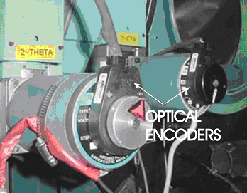
2. High Level DesignIn scientific laboratories stepper motors are used to mechanically position just about everything: monochrometers, diffractometers, translation stages, slits, optical tables, etc. Historically, stepper motors have been used because they stand up well to radiation, can in many instances be used open loop, are relatively simple to interface, and are cheap. Unfortunately, for critical applications, any slippage of the motor shaft ends up corrupting data, hence our interest in knowing the angular position of the motor shaft.
The picture on the left above is of two stepper motors with optical
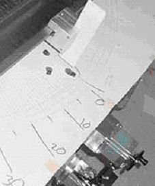
encoders on a four circle diffractometer. On the right is a hand drawn
‘dial’ indicator which uses a paper clip as a reference marker; in the
lower right hand corner are two stepper motors. 3. Design SpecificationWe take the basic definitions of user and dial coordinates as well as
the definitions of motion and rates of motion which follow, as the
specification for our controller system. From this basic specification, a
communications protocol is then established, as well as the basic control
language used to control our ATmega32 motor controller. The hardware
interfaces which we have implement naturally fall out of the specification
which follows. 3.1 Definition of Rates and Units3.1.1 Base rateBase rate is also called start rate, velocity base, base frequency or
start frequency. Usually the base rate has units of Hertz but it is useful
to think in units of steps per second. By abuse of language, steps per
second is really microsteps per second and a step pulse is a microstep
pulse.
3.1.2 Steps per degree/mmThe user is interested in the final movements of the stepper motor,
such as one millimeter or one degree. As such there is a conversion factor
defined for a given motor which relates steps, or in our case microsteps
to the user units of degrees or millimeters. If you take the output shaft
of a stepper motor as the movement you are interested in: the stepper
motor has 200 steps/rev. and the MD1 Microstep Drive has 10 microsteps/step
for 2000 microsteps per revolution. Given 360 degrees per revolution the
conversion factor is 50/9 microsteps per degree or inversely 18/100
degrees per microstep; so each microstep is = 0.18 degrees of arc
movement. The foregoing is for the output shaft of the stepper motor.
Accordingly, if you affix a 10:1 gear reducer on the stepper motor then
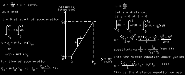
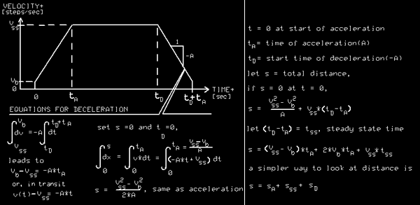
the output shaft will move 0.018 degrees of arc per microstep. 3.1.3 Acceleration timeOur motor controller uses a constant acceleration or linear velocity
ramp to accelerate to its steady state velocity, Vss, followed by a period
of constant velocity and ending with a similar period of constant
deceleration to a stop. The time of acceleration is made equal to the time
of deceleration.
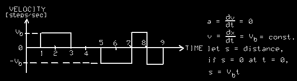
3.1.4 Forward movementShown below is the velocity profile of a complete forward movement of a
stepper motor. By convention for scientific instruments forward movement
is positive movement and is the direction in which data are gathered.
Forward movement is the scan direction.
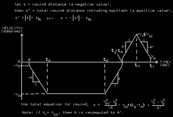
3.1.5 Reverse (rewind) motion with backlashShown below is the velocity profile of a complete reverse movement of a stepper motor. This movement ends with backlash compensation so the motor always works into the load in the same direction thereby minimizing errors. The units of backlash are steps. By convention, for scanning instruments the reverse direction is negative and is often called the rewind direction. In a typical experiment scan movements are small amounts of movement after which data is gathered, then the cycle is repeated; small scan step, gather data ….repeated scores of times. Finally, the instrument is rewound to its initial position, called a rewind motion, and another scan is initiated. It is at the end of a rewind motion that backlash is applied.
The equations for total distance traveled are also given for reverse
motion. . The math confirms that there are basically two equations needed
to calculate total distance traveled, (1) an acceleration/deceleration
equation and (2) a steady state equations. A basic rule of thumb is that
backlash should be between 1/10th and 1/20th of a degree or millimeter;
therefore backlash should have a value 1/10th to 1/20th of the conversion
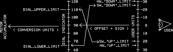
factor. 3.1.6 User UnitsOur motor controller uses units of degrees or millimeter and we support
the use of a dial indicator. Rotating instruments come with ruled marks on
the rotating part of the instrument while on the non-rotating part of the
instrument there is an indicator mark. The same holds true for translating
instruments. The measuring rulers are referred to as dial indicators and
measure physical units. When the instrument is installed and the scan
direction is defined it often turns out that the dial runs counter to the
user units. The utility of the dial comes when the instrument ‘loses
position.’ The dial is then used to ‘recover position.’ user_units = (sign * dial_units) + offset (1) Dial units are taken as directly proportional to the hardware value in the
motor accumulation. Note that the conversion factor can be negative, and
this is exactly what is done when the user wants to change the sense of
his user units. If you have a case where the dial units run counter to the
user units then sign = -1 and if the conversion factor is also negative
then as the motor accumulator increases the user units will also increase.
3.1.7 Relative and Absolute MovementOur motor controller has the ability to move to any valid relative (within
software and hardware limits) user unit. It also has the ability to move
from its current position to any absolute position providing the end
position is within its valid limits. 3.2 Command ProtocolThe personal computer communicates via half duplex RS-485 communications
with the ATmega32 UART. The motor controller is always a slave and the
personal computer is always the master in our system. 3.2.1 Packet StructureThe packet structure for data being sent to the MID consists of six bytes: MID address ! Command R/W ! Data[0..7] ! Data[8..15] ! Data[16..23] ! Checksum The ! symbol means concatenation. No spaces are allowed in the string. The
motor controller has an address with the value 1 to 127 (bit D0 to D6) and
the MSB (D7) is 1. A read or write command (1 for write, 0 for a read
query) is determined by the MSB of the Command instruction. A parameter of
up to 24-bits can follow in the next three bytes. The range of possible
parameter values is given in the next section. The checksum is an 8-bit
value which is the sum of all five bytes in the packet preceding the
checksum. MID address ! Command ! Return
code ! Return value[0..7] ! The MID address is the address of the MID sending the packet to the master
controller with the MSB = 0x80. The Returned value shall be specific to
certain commands. The Return codes shall are defined below. The checksum
shall be the 8-bit sum of all preceding six bytes. 3.2.2 Command SetShown below are the commands which our motor controller supports.
|
|||||||||||||||||||||||||||||||||||||||||||||||||||||||||||||||||||||||||||||||||||||||||||||||||||||||||||||||||||||||||||||||||||||||||||||||||||||||||
Value Returned |
Meaning |
Description |
| 0 | EVERYTHING OK | Proceeding with command |
| 1 | COMMAND NOT VALID | Invalid command |
| 2 | MOVE STOPPED | Massive slippage, move stopped |
| 3 | MD1 NOT ENABLED | Motor driver not enabled |
| 4 | MOTOR SLIP COMP. | Compensating for slippage |
| 5 | INTERRUPT | Hardware limit triggered |
| 6 | SOFTWARE LIMIT | Software limit triggered |
| 7 | CHECKSUM ERROR | Checksum error on incoming command |
3.3 Interface Specification
3.3.1 RS-485 interface
Our motor controller uses a MAX487 for RS-485 communications. Spike suppression is provided as well a high frequency termination of the RS-422 signals.
3.3.2 SPI interface
The MID can be FLASH programmed using the Serial Peripheral Interface on pins PB5, PB6, and PB7.
3.3.3 MD1 interface
The MD1 interfaces with our motor controller via 4 signals: (1) + 5 volts DC, (2) Step command, (3) Direction command, and (4) an enable/disable control signal. Even though the MD1 is optically isolated a ferrit bead inductance will be used to reject noise from the MD1. Open collector buffers are used on the motor controller as Step and Direction buffers. An opto-isolator is used to isolate the MD1 enable/disable signal. When the motor controller first powers up the enable/disable signal is LOW, that is, in a disable state and Step and Direction are HIGH.
3.3.4 Encoder interface
The +5 volts DC to the optical encoder is isolated with a broadband ferrit bead. The differential RS-422 signals from the optical encoder are physically interfaced with a 10 pin head which has the same layout as the optical encoder.
3.3.4 LCD interface
The LCD interface identical to the one used in lab and is shown on page 4 of the schematic.
3.3.5 JTAG interface
Our motor controller has a JTAG interface to support future testability and maintainability requirements of our design