or
How I Learned to Stop Worrying and Love ECE 476
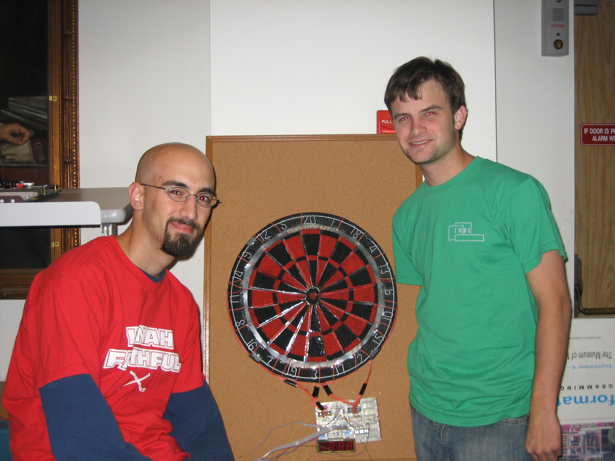
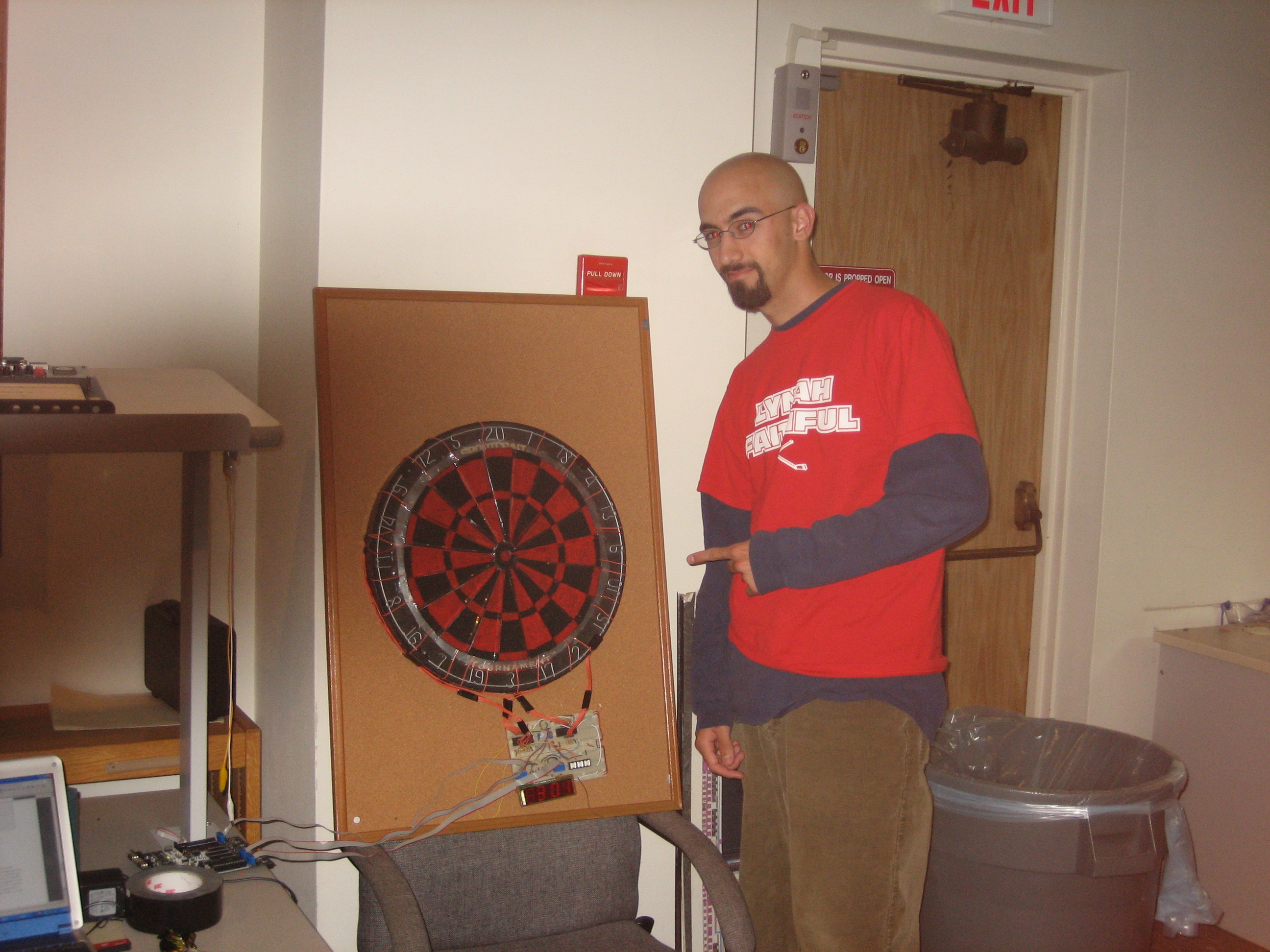
Mark Campbell
and
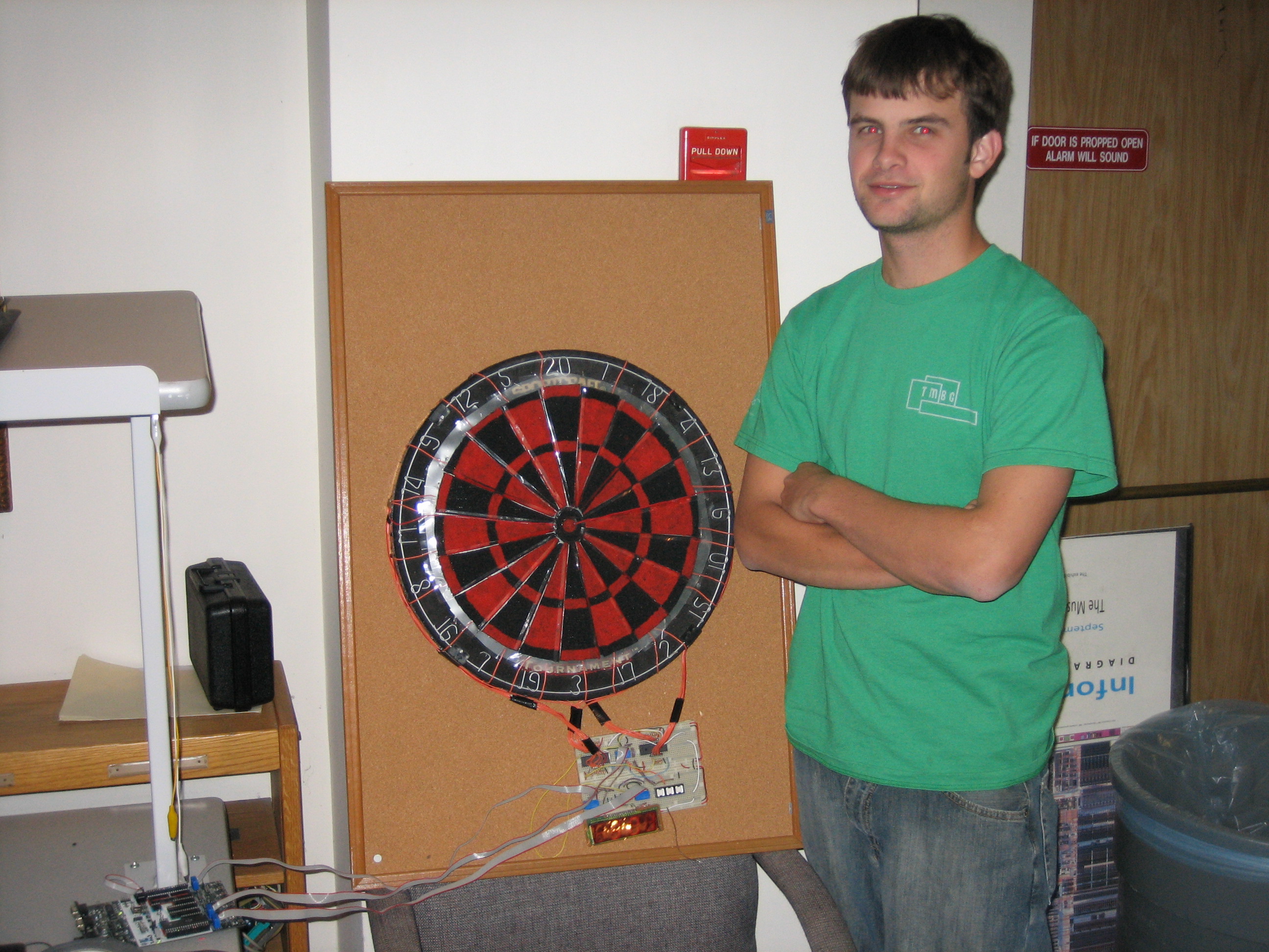
Curtis Henkel
Final Project
May 6, 2005
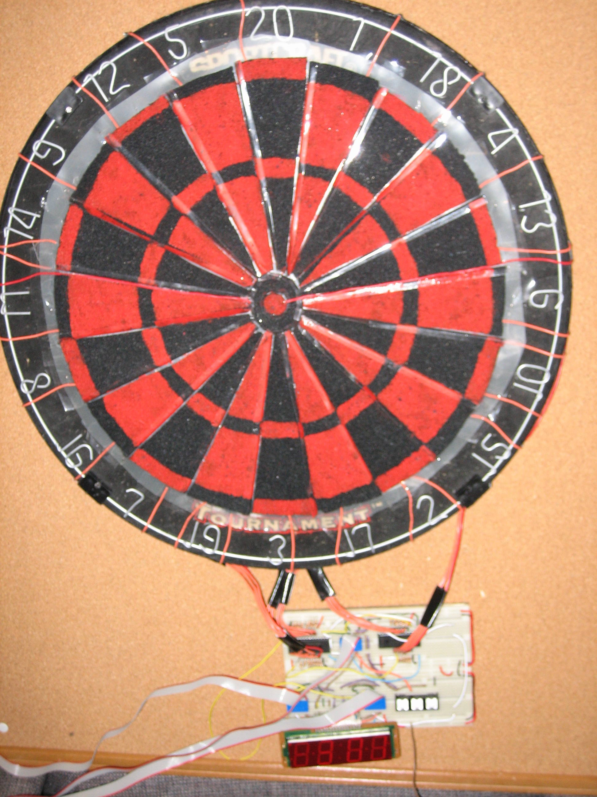
Table Of Contents
Introduction
High Level Design
Program/Hardware Design
Results
Conclusion
Appendix
Pictures
Introduction
Ever dream of having a
darts game scored automatically without using those annoying plastic
darts? We decided it was a dream most of us has had at some
point, and so decided to implement an automatic scoring system for a
“real” cork dartboard.
As college students, we found darts to be a great way to pass time and relax. After our sophomore years, we considered ourselves to be fairly serious darts players, and decided to upgrade from an electronic dartboard to a cork dartboard, but were very frustrated by the lack of automatic scoring. Thus, the motivation behind our final project was borne well before we knew our project existed. When we saw our darts dream as a possible application of microcontrollers, we did not let the opportunity pass.
So, for our project, we designed a “real” electronic dartboard. Score was kept on an alarm clock LED, which we harvested from Curtis’s broken alarm clock. Users were able to play two games on our board: 301 and cricket.
High Level Design
We decided to undertake
this project not only for our own benefit, but also for the benefit of
all those potential darts lovers who are initially intimidated by cork
dartboards and keeping score themselves. Curtis owned an
electronic dartboard, and Mark owned a cork dartboard, and by our
powers combined we made an electronic cork dartboard.
We detected darts using two layers of Electrostatic Dissipation (ESD) Foam, a voltage divider network, two 16 to 1 analog multiplexers, and the A/D converter of the Mega 32 microcontroller. The first layer of ESD foam detected which of the 20 numbers was hit, and the second layer detected which of the rings (single, double, triple or bulls-eye) were hit. Players’ scores were displayed on an alarm clock LED harvested from Curtis’s broken alarm clock.
Initially, we were amazed that no one had thought of this seemingly great idea first. We imagined that if someone could implement such a dartboard effectively, there would certainly be a market demand. Because there did not seem to exist anything similar to our design, we were not worried about interfering with existing patents or copyrights.
Program/Hardware Design
Hardware
There were several major obstacles to implementing automatic scoring with “real” darts. The most difficult obstacle was determining the position of darts accurately. There are 82 separate areas on a dartboard; 20 numbers, each with 2 single areas, 1 “double” ring where darts count for twice their numeric value, and 1 “triple” ring in which darts count for thrice their numeric value, a single bulls-eye (the outer bulls-eye ring), and 1 “double” bulls-eye where hits count as two bulls-eyes. Each of these areas needed to be separated from its neighboring area with accuracy to within a millimeter. A great deal of our design time was used devising a feasible scheme to detect the darts.
Detecting Darts
We threw around several ideas to cross this bridge. Our initial idea was to use three optical position sensors around the board to detect a dart and triangulate its position. But this idea did not come to fruition because the price of our parts was constrained to $50. We found it impossible to find optical sensors with millimeter accuracy over the 18” diameter of a cork dartboard for under $100, let alone three for under $50.
Our next idea was to magnetize the darts we threw, and place cheap hall effect sensors on the back of the dartboard to detect dart hits. We knew we could buy Hall effect sensors for around $1, so these initially seemed attractive. The problem with Hall effect sensors is that while they are cheap, they are not accurate. We knew we would need more than 30 sensors to get the accuracy we needed, and with a budget of $50 we could not afford more than 30 sensors.
At this point we were stuck and close to changing projects entirely. We talked to Professor Land to see if he had any other ideas. He suggested using two layers of aluminum screen, separated by an insulating sheet of a material like Mylar. Using this scheme, one combination of wedge and ring would be connected at any one time. Using this knowledge, we could feed the voltage to the A/D converter and decode which ring and wedge had been hit. This presented a different problem, though, because with a metallic conductor like aluminum, voltage would either be high or low, and we would not be able to detect two darts in the same number or in the same ring. Still, this seemed like a good suggestion, if we could bypass the conductive nature of the aluminum.
When we presented this new problem to Professor Land he suggested ESD foam as a possibility. ESD foam is a foam which has a finite resistance that is not zero. We decided ESD foam would be our best chance to get reliable accuracy on the board without forcing players to throw one dart at a time so we order some from Foamtech Corporation in Massachusetts. This is a schematic of our final hardware design for detecting darts.
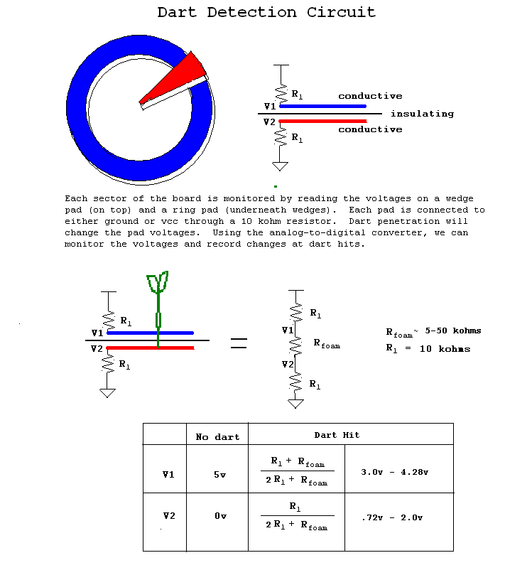
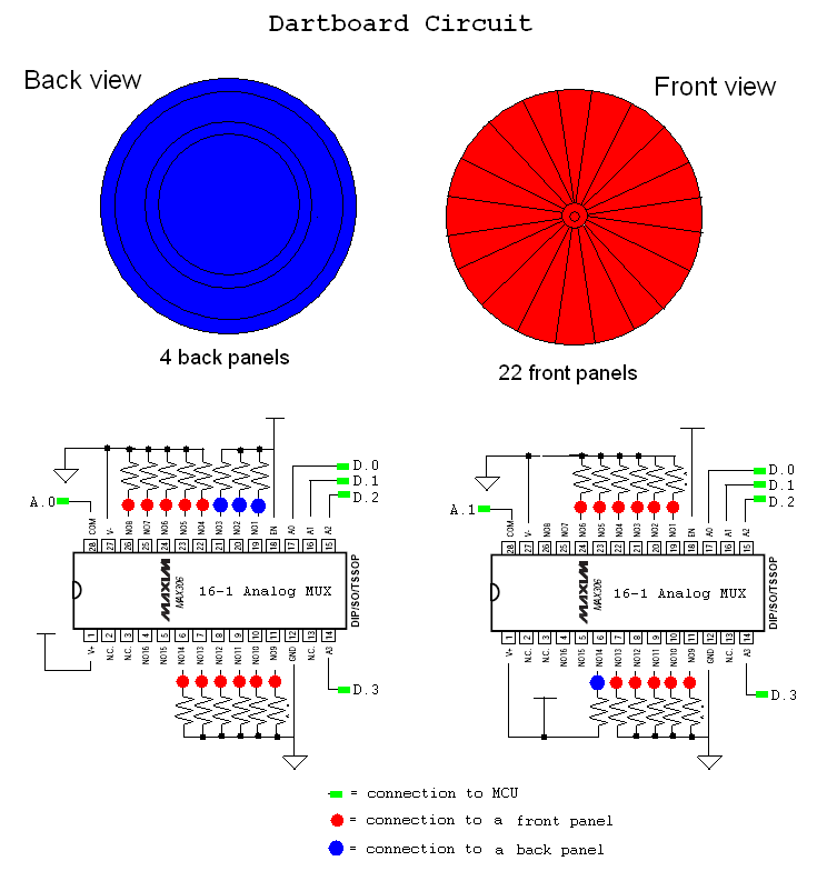
The next hurdle to overcome was the pin limitation on the Mega32 MCU. We needed to constantly scan
20 number wedges, and 6 rings (2 singles, 1 double, 1 triple and 2 bulls-eyes) in order to detect a dart hit, but only had 8 A/D converters on the chip. We realized this and sampled 2 16:1 analog multiplexers, the MAX306, from Maxim-IC. This was ideal because it solved the problem of too many pins and did not cost anything.
In practice, though, this was the most unpredictable part of our circuit to debug. To initially test, we connected all the muxes to the whiteboard and tested a portion of the dartboard. After the whiteboard connected to the STK500 worked properly, we soldered the the analog muxes, the buttons, the LED and the connecting wires to the breadboard and our custom PC board and retested. To our dismay, the circuit was no longer functional. The pads were at the correct voltage, but the AVcc on our custom PC board was too unstable to get a good A/D reading. After spending more than 2 days finding this bug and attempting to fix it, we gave up and reconnected the circuit to the STK500 and the whiteboard.
After finding that a pin of the analog mux didn’t work, and eventually switching to another pin, we finally had the capability to detect darts accurately. This was by far.
Certainly, this was the most difficult aspect to implementing electronic scoring on a cork dartboard. Appropriately, then, we spent the most time designing, implementing, and debugging this part of the project. For all these reasons, it is also the aspect of our design we are most proud of.
Displaying Scores
The next challenge we faced was displaying the darts we had detected. We knew that it could take our entire budget to simply detect the darts, and didn’t want to spend 8 of our precious 50 dollars on an LCD. For this reason, we decided to take apart Curtis’s alarm clock and see if we couldn’t utilize it. After we disconnected the LED and found the datasheet online, we were able to display any number we wanted on the LED. As specified on the diagram and table below, there are 16 inputs to the LED; two of the pins correspond to the cycle, and the other 14 pins control the lights on the display as well as the AM/PM lights and the colon. Each individual light on the display is turned on when it is high and its cycle is on. The cycles are changed at a frequency of 62.5 Hz (close to 60Hz, which is used during normal clock operation). We then decoded the 32 bit values (16 bits, 2 cycles) that corresponded to each number and each digit. Also, we decoded the 32 bit values that corresponded to the scores for the game of cricket.
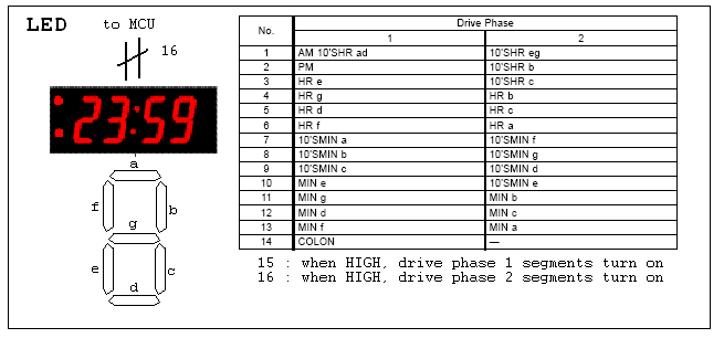
For the cricket scores we used the scoring system on Curtis’s electronic dartboard as a model, and implemented it on our LED. For some background, the game is won when a player hits the numbers 15, 16, 17, 18, 19, 20, and bulls-eye three times and has the most points. Player A would score 20 points on player B, for example, when player A has hit three 20’s, player B has not, and player A hits another 20. The number of times a player has hit 20 is recorded on the f, a, and b LEDs of the hour digit. 19 and 18 use the same leds on the 10’s minute and 1’s minute digits, respectively. Likewise, the 17, 16, and 15 are kept on the c, d, and e LED’s on the 1’s minute digit, the 10’s minute digit, and the 1’s hour digit, respectively. The bulls-eye’s are kept on the g LED of the same digits. These were not difficult to implement, they were just decoding more outputs to the LED.
Button
Detection
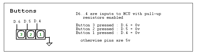
The final portion of our hardware involved the buttons with which a player chooses a game and interacts with a game as it is being played. We received the buttons as surplus from the ECE lab and thus didn’t need to pay for them. They essentially worked the same as the 16 button keypads we used in previous ECE 476 labs, except they only had three buttons. One button on the terminal was connected to ground and the three button pins were pulled high as inputs. When a user pressed a button the input was pulled low to ground. Using this, we were able to detect when a button was pushed and respond accordingly. This is a diagram of how the buttons actually worked:
The final portion of our hardware involved the buttons with which a player chooses a game and interacts with a game as it is being played. We received the buttons as surplus from the ECE lab and thus didn’t need to pay for them. They essentially worked the same as the 16 button keypads we used in previous ECE 476 labs, except they only had three buttons. One button on the terminal was connected to ground and the three button pins were pulled high as inputs. When a user pressed a button the input was pulled low to ground. Using this, we were able to detect when a button was pushed and respond accordingly. This is a diagram of how the buttons actually worked:
Software Design
The software aspect of this lab can be described simply by saying that we needed our software to respond to dart hits and button presses, and control the LED’s. We also needed state machines to control the button debounces, the dart hit debounces, and the LED updates.
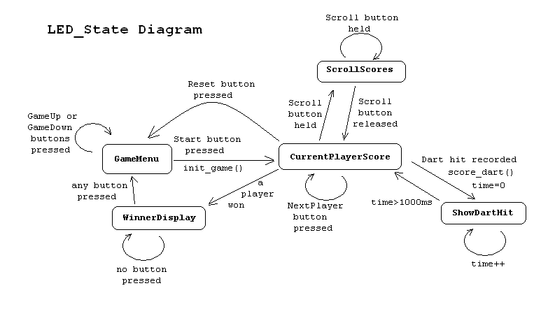
LED Driver
The LED driver was difficult in that we had to write code that would create a data structure that represented what we wanted to show on the LED. Since we had 2 cycles of 14 leds, we decided to encode the LED bits as a long (32-bits). We then wrote functions that will construct the proper long to display a number or letters. Using these functions then let us not worry about the correct encoding of the longs. We used a different long for each component we wanted to show: game menu, each player's score, dart numbers when hit. As the LED_State is changed, the appropriate long is used by the timer interrupt as output to the LED. Since there are two cycles, we need to output only half of the long at a time and flip the cycle bits (15,16) to the LED. The timer interrupt will swap the halves every 8 milliseconds. This means that the LED segments are actually flickering at 62.5Hz, which is higher than the human vision system's flicker threshold (i.e. the fastest rate of change that is perceived as a flickering object) so the LED appears as a constant display. This is was our state diagram for the transistions between LED displays:
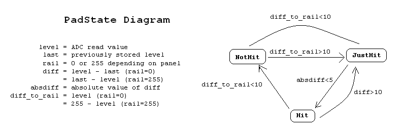
Scan for Darts
The next part of the software we designed was the software that scanned for the dart hits. The routine was fairly simple. We changed the select bits of the analog multiplexers, to select different bits from the 16:1 mux, then change the internal A/D mux from pin A.0 to pin A.1 depending on which of the two muxes we wanted to read from. If any values were more than 10 mux levels off of their rail (255 of 0 depending on whether the pad was connected to power or ground) we determined that the pad was hit and moved it to the “Just Hit” state. After the readings from the pad stabilized we moved it to the “Hit” state. When we found two pads in the Hit state, we decoded the pads to actually score the dart for the current game, and then returned the darts to the “Not Hit” state. Most of the complexity of this stage is hidden in the hardware technology of the MCU’s internal A/D converter and the MAX306 analog mux. This is the state diagram of our dart detection software:
Button Debouncers
This was by far the easiest part of our project in terms of both hardware and software. In fact, the buttons we used were almost identical to the keypad we had worked with in previous ECE 476 labs, so we essentially copied our code from those labs and pasted into this project. We debounced the button presses, then added new functionality when we detected the buttons were pressed. This is our button state machine
Results of the Design
In general, we found
our design to be sufficient to our needs for this project. We
detected the vast majority of dart hits and recorded them fast enough
for a reasonable game of darts. We truly could not ask for more
of our design, given the specification for such high accuracy over such
a large area.
Speed of Execution
In terms of speed of execution, we found that switching mux values extremely quickly was not prudent in terms of accurately reading the ADC. We also wanted to give the board pads time to settle in a state before decoding them. This caused our execution to be acceptable, but not great. In general the user may have to wait a second after the dart hits to in order to see whether it was scored properly. This could only be a problem if a user wanted to throw three darts very quickly, in which case it the board may score the second dart before the first. Still, we considered this to be acceptable for the vast majority of users
Accuracy
The dartboard, overall, was extremely accurate when the darts were scored. With very few exceptions, darts that hit the board were scored in the correct number and the correct ring. There is one diabolical case, however, which we were not able to get around in our design. This was the case in which two darts, of a players’ three, hit the exact same wedge and the exact same ring. Because the circuit was already connected by one dart, the addition of a second dart didn’t change the voltage level of either pad and couldn’t be scored consistently. We worked around this by taking both darts out after a player’s turn was over and reinserting it in the same pad, in order to force the board to recognize the score. This did not seem to us to be a great distraction as it is very rare and, even when two darts do hit the same area, it is not difficult to work around.
Safety, Interference and Usability
We mainly relied on people’s common sense to not throw darts at other people, as most manufacturers of cork darboards do.
In terms of interference with other projects, there was nothing significant that would interfere with our project short of an electromagnetic pulse bomb.
The dartboard was initially designed for our use and not for general production. For this reason, it is not very user friendly for the general public. However, extending this usability would simply be a matter of placing a menu displaying button functions in different states. However, since we were the only people playing darts with the board, we did not consider it a high priority.
Conclusions
Results
versus Expectations
In general, we considered our results to be overwhelmingly positive. We were not certain, when we began our design, whether detecting darts with such great accuracy over such a large area was possible. Our design was original (or at least independently conceived) in that we are not aware of anyone else implementing such a scheme for darts. We designed the circuit for the voltage divider and the state machine to detect dart hits, as well as programmed two two player darts games.
There are some bugs, most notably the fact that two darts in the same area are usually not detected. If we had to do this project again, we would probably try to make it more robust by connecting two wires on each side of the pad, and use 4 16:1 analog muxes. Using this scheme a second dart in the same area would almost definitely cause a closer path (and a different voltage) for each of the pads, and we could effectively detect this problem. Still, there is still a problem in the three darts in the same area would still not be guaranteed to change the voltage of the pads, and so the dartboard wouldn’t be fully functional anyway.
Adherence to Standards
As the only applicable standard was the tournament rules of the American Darts Organization (ADO) we obviously attempted to conform completely. Practically though, we could not could the double rings in a perfect circle, or the wedges at the exact angles. These shortcomings really could not be avoided, and was really not our primary concern in our design.
Intellectual Property Issues
We are proud to say that credit for the design belongs solely to Professor Land, our TA Steven Keiper, and ourselves.
Appendix
Cost
Detail
| Part |
Quantity |
Cost |
| STK500 |
1 |
$15.00 |
| Power Supply |
1 |
$5.00 |
| Whiteboard |
2 |
$6.00 |
| ESD Foam |
~3'x5' |
$13.00 |
| Mylar |
4'x1' |
$2.00 |
| MAX306 Mux |
2 |
$0.00 |
| LED display |
1 |
$0.00 |
| Cork backing |
1 |
$0.00 |
| Total |
$47.00 |
Specific
Tasks of Each Partner
The vast majority of our work was done collaboratively and together in lab. Below are most of the important tasks which were divided between us.
Curtis
- Decoded LED
- Wrote LED and Button State Machine
- Painted Dartboard
- Wrote 301 Game
- Drew Report Schematics for Webpage
Mark
- Soldered Custom PC Board
- Wrote Cricket Game
- Wrote Cricket LED Scoring
- Wrote Report and Webpage
Collaboratively
- Cut ESD Foam and Glued Pieces to Mylar and Dartboard
- Debugged Software
- Debugged Hardware
- Soldered Custom Breadboard
- Wrote Hit Scanner and Decoder
- Set up whiteboard circuit
- Cut Wires and Resistors
- Became Frustrated with A/D converter
- Ordered Wings over Ithaca and Pita Pit
References Used
We used the data sheets for the Sanyo LM8562 Digital Alarm Clock to decode the LED, the datasheet for the MAX306 from Maxim-IC to decode the Analog Muxes, and the datasheet for the Atmel Mega32 to decode the microcontoller
We used the data sheets for the Sanyo LM8562 Digital Alarm Clock to decode the LED, the datasheet for the MAX306 from Maxim-IC to decode the Analog Muxes, and the datasheet for the Atmel Mega32 to decode the microcontoller
Pictures