|
|
|
Soundbyte:A Wireless Data Telemetry system that receives acceleration, proximity and external temperature data from a remote vehicle and displays them on an NTSC television screen.
The rationale behind this project is to provide the user with information regarding the vehicle’s acceleration, proximity to other stationary objects, and external temperature. The information gathered would be useful if the vehicle is used to explore unfamiliar terrain. The vehicle is controlled by a small hand-held remote control with two joysticks (up, down, combination of both) that can make the vehicle go forward, backward and turn. The focus of the project was to design and build a wireless telemetry retrieval communication system that effectively communicates pertinent data using packets.
[back to top]
|
Our design consists of a microcontroller and several sensors mounted on the remote controlled vehicle to gather information about the vehicle and broadcast the information through a transmitter. The key focus would be to detect mechanical motions of the car and its surrounding conditions through the use of accelerometer, temperature sensor and infrared distance sensor. The information gathered is then encoded using a microcontroller and sent through a transmitter. At the receiver, we use another microcontroller to decode the received data packets and display the parameters on a TV.
Rationale and Sources of Project Idea:
We consulted several project websites from previous years to get an idea of what we can do with an RC car. We knew we wanted to incorporate a remote controlled vehicle as part of our design project. Our initial idea was to hack an RC car and implement additional features; however, after consulting Steve Lowe (one of the TA’s for ECE 476) about the RC car he built, we decided it would not be worthwhile to try to find a non-existent spec sheet on a customized microcontroller chip within the RC car. Hence, we decided to leave the car as it is [much to the appreciation of Tiffany’s sister whose car we borrowed] and design a stand-alone wireless communication system that would gather information about the vehicle’s surroundings.
Projects we consulted:
Background Math
There is very little background math required for this project other than the usual expected out of an ECE junior. The primary focus of mathematical calculations is the wireless communications: the data transfer rates, the timing, and the data encoding. Although background in Error Control Code theory would be helpful, it is not entirely necessary.
Logical Structure
Our design project consists of two major components, the car (transmitting end) and the home base (receiving end). The wireless telemetry system was designed as a stand-alone system consisting devices that can be attached to any moving object to detect its acceleration, surrounding temperature and distance from surrounding stationary objects.
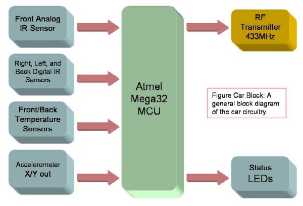
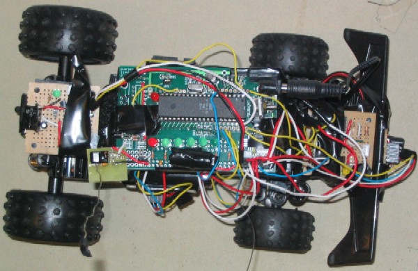
On the car (Figure Car.Block), we have several sensors to gather data from the surrounding environment and an AtmelMega32 microcontroller chip used to process the gathered data, which is then encoded into appropriate data packets and sent via the wireless transmitter at 433MHz. The sensor system on the car base consists of two temperature sensors (front and back), four IR sensors (two on the side, one front and one back) and one accelerometer (which measures both X and Y direction acceleration). We also included status LEDs on the CPU board to help with hardware debugging.

On the home base (Figure Base.Block), we receive the data packets from the transmitter via a 433MHz wireless receiver, and use another AtmelMega32 microcontroller chip to process and decode the received data packets. We then format and display the gathered data onto a TV screen. There is also a set of LED’s to facilitate debugging as well as make pretty light patterns to keep the user thoroughly entertained.
For the wireless communication network, we used radio waves (433MHz) to transmit and receive the data packets. Both the transmitter and receiver chips are mounted on the microcontroller boards. The receiver chip is soldered directly on the home base CPU board, the transmitter chip sits on a separate PCB board, but it attached to the car base CPU board. We consulted the spec sheets for design layout, overall the circuitries for the transmitter and receiver are relatively simple and straightforward to design and build. Professor Land suggested that we include a homemade inductor to deliver more power to the antenna, thus effectively increasing the range of the wireless transmission. The details of hardware design are explained in the next section.
Hardware/Software Tradeoffs
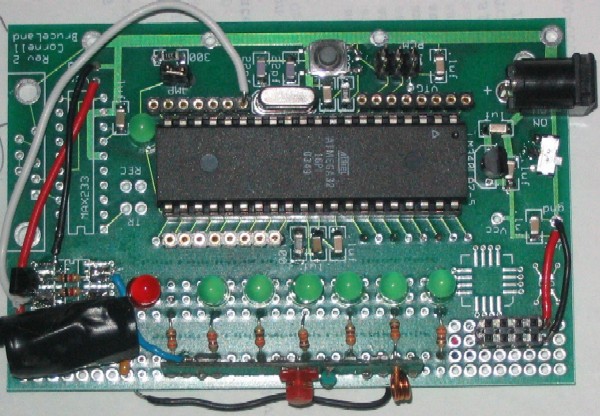
We built two customized PCB’s for the two microcontrollers we used. We also built several separate pieces of Radio Shack through-hole solder boards that contain the circuitry for the analog IR sensor, temp sensor, digital IR/temp sensor and accelerometer. We also added 7 colored LEDs onto each CPU board for debugging purposes. Overall, our soldering and debugging efforts for the hardware portion of our project took up roughly 75% of our time. This is the first year that surface mount components were used in an ECE 476 final project, the customized CPU board was designed for this purpose. The surface-mount components we used this year made the circuitry a lot easier to maintain, we didn’t have to deal with extra wires and large components with loose connections. As a result of using printed circuit boards, we had to solder under magnifiers and use extra fine tipped soldering irons to make the board. Nonetheless, it was a fun experience and a useful skill to acquire.
Following the logic of the hardware, the software was split up into two portions. Generating and debugging the software took a considerably shorter amount of time then getting the hardware working. Because our final project is so sensor centered, it is very hardware intensive. The software merely collects, manages and processes the data these sensors spit out; as long as the hardware works, the software is going to perform. Overall, the software occupied 25% of our times in terms of debugging and composing. Obviously the home base software took significantly more time than the car, for reasons explained in the software design section.
Professional Standards (FCC, UL, RS-170, RS-232)
There are several professional standards we must meet for our design project. We included them in the table below.
| Professional Standards |
| Federal Communication Commission Standards (FCC)
|
Transmission frequency regulation
|
| Underwriters Laboratories Inc. Listed (UL listed)
|
Electrical device safety
|
| RS-170
|
Black and white TV video format
|
| RS-232
|
Serial communication protocol
|
Consumer grade remote controlled cars must meet the Federal Communication Commission (FCC) standards. The RC vehicle we are using for this project is an over-the-counter (OTC) consumer product; therefore we do not need to worry about conforming to the FCC standards (we assume that it already does). We are concerned with designing a wireless communication channel that meets the FCC standards. The remote controlled vehicle we used operates at 27MHz, the wireless communication network we designed operates at 433MHz; thus, the two operating frequencies do not interfere with each other.
In addition to the FCC standards, we conform to the Underwriters Laboratories Inc. Listed (UL LISTED) standards. UL listed standard is a set of testing standards for electrical equipments and products that assures its safety. In order for a product to carry the UL Label, the product must be independently examined and evaluated for safety. We believe that our device is safe to use, but it should be used responsibly. The stand-alone wireless communication system should not cause any harm or damage if operated under normal conditions and with precaution. However, we make no guarantees of safety, since the wireless communication system will be mounted on a radio controlled car, which might cause harm to small pets and children. We will try to avoid dangerous and potentially hazardous situations by not bringing pets or small children in the laboratory. Note that the voltage regulators tend to get hot and should be avoided when the system is in operation.
Since we generate TV signals as a part of our project, we must meet the RS-170 standard; which is the standard black and white video format used in United States (defined by 525 lines 30 frames per second). For the purpose of our project, we do not interlace signals, (instead of using interlaced refresh rate of 30 frames per second, we use non-interlaced refresh rate of 60 frames per second). Also, since we have limited memory available to us, we only use a 262 line scaling instead of a 525 line scaling.
We are using the RS-232 protocol to interface between the microcontroller and the wireless receiver and transmitter. The RS-232 protocol was developed to provide a greater distance for reliable serial communication via physical wire connection. It is mostly used as microcontroller-PC communication.
Relevant Existing Patents, Copyrights and Trademarks
Wireless telemetry system technology has many applications; it is especially well-suited for monitoring and controlling remote devices. Our wireless telemetry system is a modification of this generic technological concept (only monitor, no control), in that we sample and record data of the physical surrounding and send the data via a wireless transmitter. There are many existing telemetric systems in the market, we included the following websites for your reading pleasure. We assume the technologies featured in these websites have patents.
[back to top]
|
Home Base

The following diagram, Figure Base.Schematic, illustrates the hardware layout for the receiving end of the wireless communication system. PortA are connected to seven LEDs, PORT D.0 is used to receive the transmission data, and PortC (C.5 an C.6) is used to connect to the TV. A voltage regulator circuit (upper left) is used to regulate the voltage for the CPU board. We are using an 11V AC power supply to power the circuit; it is converted to 5V using LM340-LAZ5 voltage regulator, with a maximum output current of 100mA. The regulated voltage is delivered to all of the components on the CPU board, indicated by the red colored wiring. XTAL2 and XTAL1 are connected to a 16MHz crystal, which is used to clock the CPU. Reset pin is connected to a reset pushbutton and a 100K resistor. The TV circuitry (Figure Base.TV) is exactly the same as Lab 4, with the exception of using PORTC instead of D, so is the rationale behind picking such resistor values.
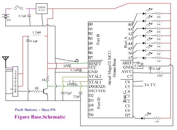
The receiving circuit consists of an antenna, a RCR-433-RF receiver, an inductor and a BJT inverter. The inductor and capacitor form an active LC filter, with characteristics of low DC impedance and high AC impedance that served to remove the effective short between Vcc and the antenna, thereby maximizing receiver strength. This setup effectively eliminates AC fluctuation from the power supply. The transmitter in its ambient state sends a constant of one. Since we do not want a continuous transmission of one we use an inverter circuit at the transmit end. Hence, another inverter on the receiver end is necessary to invert the data so that no software correction would be necessary. The antenna used is a Ľ-wavelength (18cm) coiled wire.The rest of the design of the circuit is evident in Figure Base.Schematic.
Car
The following diagram, Figure Car.Schematic, illustrates the hardware connections for the transmitting end of the wireless communication system. Port B.0-B.1 are connected to two digital infrared distance sensors: one on the starboard side and one on the aft. Port A.0 is connected to the analog infrared sensor on the forward part of the car. Port C is connected to seven LEDs, PORT D.1 is used to transmit the data packet. [Note the recurring use of LED’s connected to an 8-bit port. The reason for this is because there is not enough room in development area to neatly place 8 LED’s].
There is a similar voltage regulator circuit as the home-base circuitry described above. However there are two differences, first instead of using an 11V AC power supply, a 9V battery is used to power the CPU board. The reason for it is because the car-base CPU board will be mounted on a moving vehicle, so it is more practical to power it using a portable battery. The second difference is instead of using a LM340-LAZ5 voltage regulator; we are using a LM340-T5 instead. We found that by using a LM340-LAZ5 voltage regulator, the supplied voltage falls below 5V. The reason behind that is we have too many components on the car-base CPU board that draw too much current. By switching to LM340-T5, (which has a larger maximum output current of 1000mA) we can ensure that a constant voltage of 5 volts would be supplied to the all the components. We found that the voltage regulator becomes very hot after a while, so we added a heat sink on the voltage regulator to dissipate heat. The voltage regulator is controlled by a switch, which will turn on/off the power for the CPU board. The regulated voltage is delivered to all of the components on the CPU board, indicated by the red colored wiring. XTAL2 and XTAL1 are connected to a 16MHz crystal, which is used to clock the CPU. Reset pin is connected to a reset pushbutton and a 100K resistor.
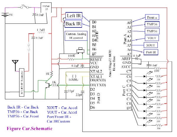

The transmitting circuit (Figure Car.Schematic) consists of an antenna, a RCT-433-RP transmitter, a hardware jumper switch, an inductor and a BJT inverter. The inductor and capacitor form an active LC filter, with characteristic of low DC impedance and high AC impedance that decouples the short between Vcc and the antenna consequent by the nature of the circuit. The transmitter, in its ambient state, sends a constant 1. Since we do not want a continuous transmission, we use an inverter to invert the output of the USART to the transmitter.
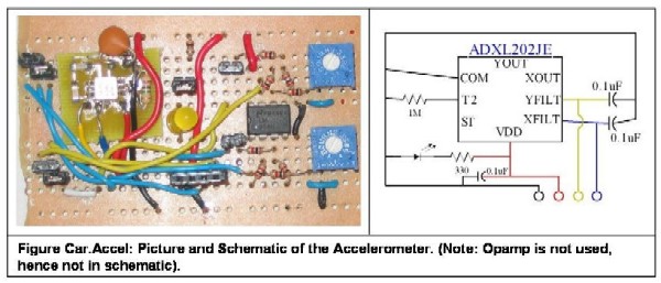
The accelerometer we are using for our design project is ADXL 202JE, we salvaged this component from one of last year’s projects. This accelerometer can measure accelerations with full-scale range of . The circuitry for the accelerometer (Figure Car.Accel) can be found on page 8 of the ADXL 202JE data sheet. RRESET is 1 M?, the XFILT and YFILT capacitance are chosen using the following formula:
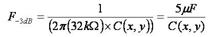
Looking at Table 1. Filter Capacitor Selection on page 9, CX and CY should be 0.10µF for a bandwidth of 50Hz. In Figure Car.Accel, the black and red wires are ground and Vcc. We are low pass filtering the output of the XFILT and YFILT to get rid of the 60Hz noise. The yellow and blue wires will contain information regarding the Y-direction and X-direction acceleration.
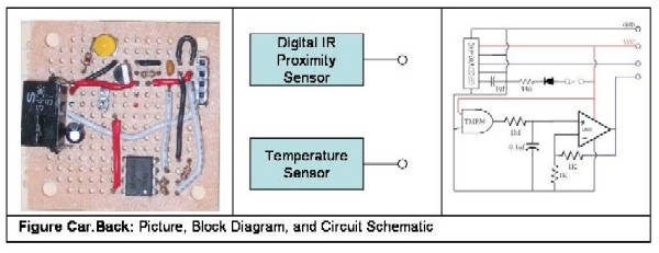
The temperature sensors we are using are TMP36GT9, which were sampled from Analog Devices. TMP36 provides a voltage output that is linearly proportional to the Farenheit temperature. We are using two temperature sensors for this project, one mounted in the forward section of the vehicle, one in the aft section of the vehicle. Before sending the data into the CPU (Figure Car.Back, Figure Car.Front), we low pass filter it to get rid of noise and amplify the output voltage by using a dual gain voltage amplifier (with matched resistors). Therefore, we ensure that the input signal to the CPU is amplified and relatively free of noise.

We used both analog and digital IR proximity sensors. The digital IR sensor we used were SHARP GP2D15 1Z (with checking distance of 24 cm) and SHARP GP2Y0D340K (with checking distance 40 cm). The analog IR sensor we used was SHARP GP2D12 36 (which detects a range of 10-80cm), the output voltage will run through an A/D converter and output the exact value of the distance to surrounding objects. The circuitry for digital IR sensor is in Figure Car.Back, the circuitry for analog IR sensor is in Figure Car.Front. Since the output of the digital IR sensor is binary, we simply take the output of the sensor directly with no amplification, but rather a pull up resistor of 10KOhm. The output of the analog IR sensor on the other hand is amplified using a dual gain voltage amplifier with matched resistance and low pass filtered to reduce the 60Hz noise. [Note: The analog GP2D12 and one of the digital GP2D15 failed and are not a part of the project.]
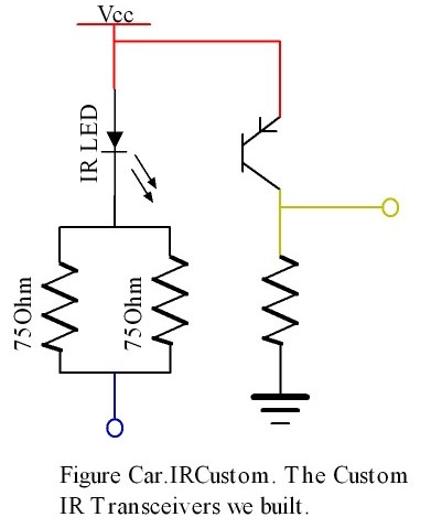
We also implemented two analog IR proximity sensors using infrared emitter diodes and detector phototransistors we purchased at Radio Shack. We consulted the data sheets for the emitter diode and phototransistor and used online references to design and implement the IR sensor circuits. For the emitter circuit (Figure Car.IRCustom), we want to maximize the power to the emitter in order to have the best detection range. On the spec sheet, the typical forward voltage is 1.2V – 1.6 V with a typical operating voltage of 1.3V. By choosing two 75? resistors in parallel (effectively 35?) and using 5V for Vcc, the voltage measured across the resistors is 3.65V, which makes the forward voltage of the diode to be 1.35V (which is close to the typical operating voltage of 1.3V). As a result, there is approximately 100mA of current through the emitter diode. Of course the transmitter is not always on, software controls the transmitter diode to be only on for a brief amount of time every 100ms. For the phototransistor circuit (Figure), we want to maximize the sensing distance. We tried several different values of the resistor; we found that by using a 20k? resistor, we have the maximum sensing distance of 4cm – 16cm.
Design Suggestions
Failed Attempts / Mistakes to Avoid
In order to reduce the cost of our project, we initially attempted to use an Atmel163 micro-controller, which is cheaper than a Mega32. However, after spending an entire lab session figuring out how some of the essential Ports do not work on the 163, we decided to switch back to Atmel32. Since we do not get a grade boost from reducing cost, we decided to save on time and finish early.
There were several set-backs while we were working on the hardware component of the project. On the customized CPU board, we failed to check the polarity of the LED, as a result we had to unsolder several LEDs. Another problem we run into is the voltage regulator on the car-base hardware. The voltage regulator we initially used was a 5 volt LM340LAZ with a maximum output current of 100mA. However, the sensors and other components of the board are drawing more than the indicated current, as a result the Vcc voltage is less than 5V. In order to correct this problem, we changed to a 5 volt LM340T5 voltage regulator with a maximum output current of 1000mA.
Towards the final days of our project, we ran into several unexpected setbacks. Two of our IR sensors got damaged during testing for some mysterious reason we have yet to figure out. The damaged sensors are the front analog IR sensor (GP2D12) and one of the side digital IR sensors (GP2D15). Since we discovered this problem in the final week of the project, it was impossible to reorder the parts and get it in a timely manner. Since IR sensor is basically an infrared emitter diode and a BJT detection diode, we can effective construct an IR sensor if you can get an emitter and detector diode. Therefore we decided to take a trip to Radio Shake (complementary car service from our wonderful TA Dan Golden) and purchased infrared emitter diodes and detector phototransistors. After several hours of work, we constructed an IR transceiver circuit that can sense approximately 4cm-15 cm. For detail of the circuit please refer to hardware design section.
[back to top]
|
Car
The software for the car is relatively simple since it involves gathering the data, encoding it, and transmitting it. There is no processing or special output involved. A giant switch statement on a status variable determines what is to occur. For the first eleven cases, if the A/D conversion is finished, then the value is dumped in the appropriate place in the data buffer, the A/D MUX is set to the next channel of interest, the conversion is started, and the status value incremented. The data are sampled at 10Hz, or once every millisecond, except for the acceleration, which is sampled at 40Hz and then averaged (4 samples at a time) to 10Hz. Once all the data is gathered, including the sampled accelerations, they are encoded using the scheme defined below, and transmitted through the USART port to the transmitter. Once this is complete, the state machine waits till the next 100ms tick to perform the same operation again. We control the IR emitter diodes as regular LED's, hence we only turn them on right before we intend to sample the A/D channel associated with the corresponding IR phototransistor output. The reason this is necessary because the IR emitter draws 100mA of current, and we do not want that much current flowing through one device constantly.
The transmission occurs continuously at a packet frequency of 10Hz. Timer0 interrupt is used to keep track of time and every 100ms the data acquisition and transmission cycle restarts. The USART port is set to 4000 baud TX only. At 4000 baud, the maximum data transfer rate is 400 bytes / second, or 20 of our 20-byte packets a second. However, we only used half of the time, in that we only transmit 10 20-byte packets a second. Hence, our apparent throughput is 200 bytes/second. However, since we only encode 7 bytes of information into this 20 byte packet, our effective data throughput is 70 bytes/second.
Base
The home base code is exceedingly more complicated than that of the Car, primarily because it involves the generation of a video signal. In order to effectively and completely receive the packets, we embedded a short piece of assembly code in place of the horizontal sync’s 2us delay. We used the 2us, or 32 cpu cycles, to execute a subroutine that takes the byte (if received) off of the UDR and dumps it into a buffer. The buffer index is incremented to keep track of the number of bytes in the buffer.
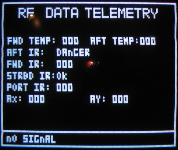
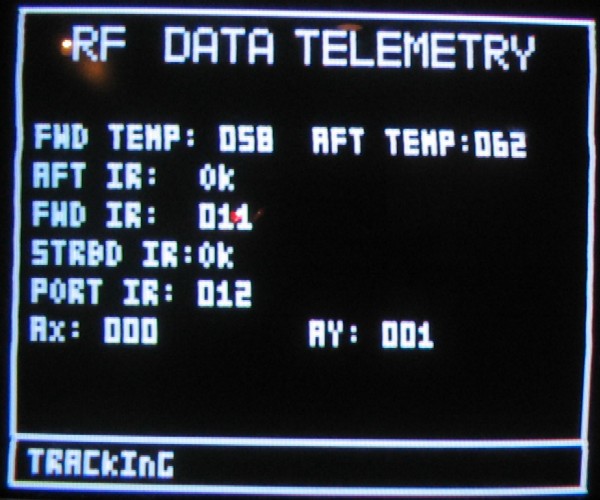
The main code checks this index, and when it reaches the maximum packet size, the content of the buffer are copied into a secondary buffer for analysis so that the index can be reset to 0 and more packets can be received. Meanwhile, the secondary buffer is analyzed for packet integrity and data. While this is happening, the TV signal generated reads the Telemetry data: a parameterized status screen with a real time updating of temperatures, IR distances, and acceleration, as well as a signal status.
We employ two levels of packet integrity checking. The first level is embedded in the above mentioned 32cpu cycles: the idea is that a packet wont be available every horizontal sync, hence if there is no packet, we create an alternate path where the last value in the buffer is checked and if it matches a packet header, the buffer count is reset. We decided not to utilize this integrity check by not sending the header byte. The second, and strongest, level of integrity checking happens once the packet is copied into the secondary buffer. We check to see if bytes 2, 3, 4 and 5 are the synchronization bytes 0xAA. If so, the packet is valid and processed; if not, then the bad packet count is incremented and the packet is dropped. When there are 5 consecutive bad packets, the system zeros all the parameters and emits a no signal status. In addition to packet integrity checking, there is a built-in error control code in the encoding scheme that is described in the following section.
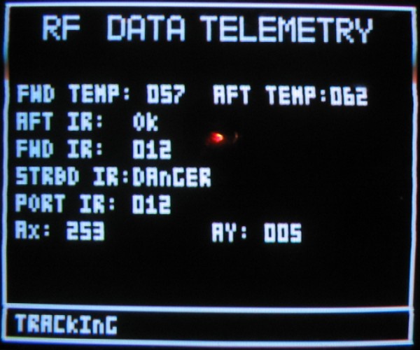
Two sets of data processing occur once it is decoded. First, the temperatures are scaled to reflect the actual value based on the scaling from the amplifier and the A/D converter. The Starboard and Back IR sensors are analyzed, if something is close, then “DANGER” is displayed, otherwise “OK”. For the analog sensors, we simply output the raw value and count on the competence of the operator to interpret the values appropriately. As for the acceleration, since the ambient sits at 128, we subtract 128 from each channel’s A/D output before displaying. Hence, a negative acceleration is registered as (128-x)-128, or 2xx.
The TV signal generation code is not describer here because it is the same code as that provided by Professor Bruce Land, and can be found here.
Wireless Communications System
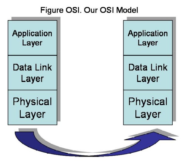
We present the above diagram as a model for our wireless communication system. It is a replica of the Open System Interconnect model used by prominent telecommunications protocols that involve packet switching. Although the OSI has 7 layers of abstraction, our model has only 3. This simplistic model is sufficient for us because we assume that we will be the only ones using the channel at any give time, and the encoding as well as the data is always fixed. The lowest layer is the physical layer which is composed of the transmitter and receiver operating at 433MHz using On-Off keying. A transmit 1 is achieved by a signal, and a transmit 0 is no signal. (Note that because of this, the data sent must be DC balanced).
The next level in our model is the Data Link layer, which is responsible of encoding and decoding the data. As an encoding scheme, we split a byte into two nibbles and encode them separately into DC-balance bytes. There are 70 DC balanced bytes, and of those we selected the ones that start with a 10. Of these, 10101010 is reserved for synch. This leaves 19 byes that can be used to map the Binary-4 space. The three that we chose to remove have the most number of ones and zeros together (which would upset the DC balancing). We use the following table as the encoding mapping:
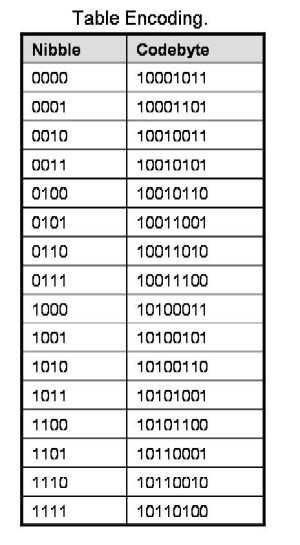
The encoding and decoding both occur through a table loop up because an exhausting search for a pattern revealed nothing. Note that there is a built in 1-bit error detection code by virtue of the DC balancing. That is, that the hamming distance between pair wise bytes is a minimum of 2. (since for any 1 that becomes a 0, another 0 must become a 1). We use this as yet another integrity check, if the received byte isn’t a valid code-byte than it is discarded.

The packet itself is composed of 20 bytes, organized as in Figure TXP. The first 5 bytes are the synchronization signal 0xaa. Then the data begins, and the last two bytes is yet another 0xaa sequence. We found this to be exceptionally reliable, so we adopted it. At the receive end, the packet looks like figure RXP. Note that the first byte is garbage, and the entire packet is shifted right by 1 byte. Hence, we match up the sync with the series of 0xaa’s and then being taking the data from byte 6 to 18. The decoding process takes each byte and converts them into nibbles, and puts them back together appropriately. With a reliable packet transmission, we can easily implement variable length packets. The first two bytes after the sync can simply be a packet length and can be extracted as a loop end constraint when processing the packet.
The next level of abstraction is the application layer. In our project, the application is either the gathering of data or the displaying of data. Hence, once the data is decoded, we are in the application layer. At the transmit side, the data is collected from the various sensors and placed in a buffer for encoding. At the receive side, the decoded data is processed at various levels. Some of the data is displayed directly to the TV, other is processed for OK/DANGER or formulaic conversion.
In sync with the nature of the OSI model, our model also contains transparency between the layers. For example, the data gathering/processing need not know how the data will be transmitted, encoded, or even received. Same at the received end is true. The data link layer can be replaced with any encoding scheme and the system would still function. Similarly the physical layer can be replaced with any other medium and system would still function. Similarly, the data link layer will encode and decode any data that is fed it without regard to its format or how it will be transmitted. Finally, the physical layer dose not care what kind of data is sent/received through it.
[back to top]
|
Speed of Execution
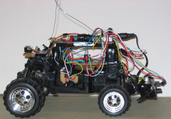
The execution of the code is rather smooth. We were cycle accurate in our assembly code and no video artifacts were noticed. We had to split up all the video updates over a period of 4 frames to ensure that the video code worked fine. The code on the car performs flawlessly because the total amount of stuff needed to do in one 10Hz cycle is less than 100ms. All updates happen in real time. The added weight of the circuit and the 9V batter has made the RC car a little bit slower.
Accuracy Measurement
The system is very accurate in terms of the measurement readings. We have an effective data throughput of 70B/s over the wireless channel. Although there is a significant amount of noise in the channel, the encoding scheme works well to correct errors in the physical layer. Errors in the data link layer are dropped and a zero value is registered. The noise in at the car affects the A/D conversion, we have no way of correcting as of now. Despite our RC filters, the values sometimes fluctuate incessantly, though within a very short range of the mean value. In order to make the accelerometer reading accurate we average 4 samples for every sample we transmit. This scheme has improved the accuracy of the accelerometer significantly.
Safety Implementation
We took several steps to ensure the safety of the hardware circuitry. We added a heat sink to the voltage regulator to prevent over-heating and possibility of a blow up. We also used electrical tape on the underside of through-hole boards to keep it from getting damaged by static electricity. To prevent wires from shorting and moving around, we kept the wire as short as possible and used duck-tape to keep the boards in place.
In terms of the possible dangers the vehicle may cause, the IR proximity sensors will detect surrounding stationary objects and sends the data back to the home-base. The remote control is designed with safety and usability in mind, and the television display would be extremely helpful for navigation. That is, the velocity and direction, as well as a trajectory will help guide the user into taking the probe vehicle wherever they want to, as well as making decision about whether or not to reduce speed. Collision detection and temperature sensing of the probe would satisfy the purpose of a telemetry retrieval vehicle: to map unknown regions and determine its feasibility for human survival.
Interference with Other Designs
There are several other groups that are using RF as a part of their design. As a result, there are several occasions where we received interference signals. However, with time we learned to yell out “is anyone using RF?” and the problem of RF interference is solved.
Usability Considerations
Our project is extremely user friendly to anyone who has operated a simple remote controlled car before. As long as you are you can operate two joysticks at the same time, this project is very simple to use. The display data is placed in an obvious manner, and everything is correctly labeled. We do require the user to have some technical expertise on the sensors so that they can realize that the units of the temperature are Fahrenheit and that the distance and acceleration measurements are just raw measurements.
[back to top]
|
Expectations
Unfortunately due to several setbacks in the latter stage of our project, we did not achieve everything we originally proposed for our design project. The predicted attainable goal for this project is to have a working vehicle that can transmit back to the home-base a sense of telemetry in the form of its current velocity and direction. We achieved this, and much more, in the sense that we had 6 other sensors running from which we were able to sample data. We planned to plot a trajectory but due to the complexity of the circuit, we were unable to come up with an effective integration technique to plot a trajectory. All the telemetry data gathered is displayed on the TV Screen for the operator.
Overall, a majority of our goals were achieved, and to compensate for the ones we did not achieve we added functionality and complexity in other directions, such as the Wireless Communication System. Our unattainable goal was an On-Car Smart turning system that would detect a collision and detect the best direction (Backward, Right or Left) and go in that direction. However, getting the sensors to work along with wireless transmission, we did not have sufficient time to explore the car’s internal motor circuitry to be able to submit it to the MCU’s will.
Applicable Standards
The remote controlled vehicle we are using for our project is a consumer product that is currently selling on the market, so it is reasonable to assume that the product meets all the safety standards. In our opinion, the wireless communication system we are adding to the vehicle will not be hazardous to the consumer. Given the fact that we are only modifying and adding components, it is in our belief that the wireless communication system (which is the focus of this design project) will not cause any harm to the consumer.
We believe all the applicable safety and professional standards have been met in our design project (including the FCC legal regulations). For more detail, please refer to the discussion of “Professional Standards” under “High Level Design”.
Intelectual Property
We believe our design project does not infringe on the intellectual property of other parties. To the best of our knowledge, we did not reuse code or someone else’s design (except those listed under “Reference Design/Code”). Since our design project is a standalone wireless communication system, we didn’t have to reverse engineer any design, thus we do not have to deal with any patent/trademark issues. Unfortunately we do not believe there is any patent opportunity for our design project, because the technology used in this project is already well developed and widely available.
Ethical Considerations (EEEE Code of Ethics)
1...to accept responsibility in making engineering decisions consistent with the safety, health and welfare of the public, and to disclose promptly factors that might endanger the public or the environment;
Our engineering decisions are consistent with the safety, health and welfare of the public, and we will promptly disclose any factors that might endanger the public or the environment. We have indicated the necessary safety precautions and noted potential hazards associated with operating such a device.
2...to avoid real or perceived conflicts of interest whenever possible, and to disclose them to affected parties when they do exist;
Through our extensive research and testing of our design project, we have isolated areas where potential conflicts might occur. We deepened our understanding of many electronic devices and the potential hazards associated with operating those devices. We have taken the necessary steps to ensure the safety of the device and promptly disclose any conflict of interest.
3...to be honest and realistic in stating claims or estimates based on available data;
We believe all the claims we made for our design project is realistic and reasonable. The claims for this design project are based on data gathered, and testing results.
4...to improve the understanding of technology, its appropriate application, and potential consequences;
We consulted several sources before embarking on our design project, in doing so we gained a deeper understanding of currently available technology in which our project is based on. We also considered the appropriate application of such technology and potential consequences associated with developing such technology.
5 ... to seek, accept, and offer honest criticism of technical work, to acknowledge and correct errors, and to credit properly the contributions of others
For our design project, we sought help and guidance from Professor Land, lab TAs and fellow classmates. We accepted honest criticism of our technical work and made changes to our design accordingly. We attributed the proper credits and thanks to those whose help was greatly valued and appreciated.
Potential Future Improvements
There is an enormous amount of room to develop this project further. The first step would be to implement some form of numerical integration to determing the exact position and bvelocity and from that plot the reali time trajectory. Second, one can implement some form of smart turning scheme. The one we recommend is a Left priority turning system, because of the layout of our sensors. The digital IR sensor on the starbord side will indicate whether there is enough room or not for a turn, if not the port side's analog IR can be used to determing if there is even the slightest bit of room to maneuver right. Also, one can always back up and then re evaluate the surroundings. The problem we ran into in the trajectory is that the X/Y of the car would change with its direction, and hence wouldnt always be the same as the screen's XY.
[back to top]
|
- Code:
- Schematic: Here is a list of all the figures in our report.
- Car.Front {pic-block-schematic}
- Car.Back {pic-block-schematic}
- Car.Block
- Car.Schematic
- Car.Picture.top
- Car.Accel {pic-schematic}
- Car.IRCustom
- Base.TV {pic-schematic}
- Base.Schematic
- Base.Block
- Base.Picture.top
- Cost Analysis
Figure Parts.List
|
Part Name
|
Model No.
|
Mfr.
|
Supplier
|
Qty.
|
Unit Price
|
Total
|
|
Atmel Mega 32
|
ATMEGA32
|
Atmel
|
Bruce Land
|
2
|
$8.00
|
$8.00*
|
|
Custom PCBoard
|
BruceLand rev2
|
PCB Express
|
Bruce Land
|
2
|
$5.00
|
$10.00
|
|
RF Transmitter
|
RCT-433-AS
|
Radiotronix
|
Mouser Electronics
|
1
|
$3.50
|
$3.50
|
|
RF Receiver
|
RCR-433-RP
|
Radiotronix
|
Mouser Electronics
|
1
|
$4.50
|
$4.50
|
|
IR Proximity Sensor
|
GP2Y0D340K
|
Sharp
|
Digikey
|
1
|
$8.03
|
$8.03
|
|
IR Proximity Sensor
|
GP2d12
|
Sharp
|
Bruce Land
|
1
|
$0.00
|
$0.00*
|
|
IR Proximity Sensor
|
GP2D15
|
Sharp
|
Digikey
|
2
|
$0.00
|
$0.00*
|
|
Temperature Sensor
|
TMP36GT9
|
Analog Devices
|
Analog Devices
|
2
|
$0.00
|
$0.00~
|
|
Dual OpAmps
|
LM358N
|
Nat'l Semiconductors
|
Nat'l Semiconductors
|
3
|
$0.00
|
$0.00~
|
|
PC Board
|
276-170
|
RadioShack
|
Bruce Land
|
1
|
$2.50
|
$2.50
|
|
Dual PC Board
|
276-148
|
RadioShack
|
RadioShack
|
1
|
$1.79
|
$1.79
|
|
Accelerometer
|
ADXL202JE
|
Analog Devices
|
Bruce Land
|
1
|
$0.00
|
$0.00*
|
|
JST Connector (M)
|
455-1273-ND
|
JST, Inc.
|
Digikey
|
10
|
$0.115
|
$1.15
|
|
JST Connector (F)
|
455-1126-ND
|
JST, Inc.
|
Digikey
|
10
|
$0.042
|
$0.42
|
|
IR Emitter/Detector
|
276-142
|
Radioshack
|
Radioshack
|
2
|
$3.30
|
$6.60
|
|
Other Lab Components
|
R's, C's, Wires
|
N/A
|
Bruce Land
|
1
|
$1.00
|
$1.00
|
|
*Salvaged from old projects, ~Sampled
|
TOTAL:
|
$47.49
|
- Individual Labor
- Meghan
- Half of Hardware Design/Soldiering
- Software Design and Implementation
- Converted Report to Website
- Tiffany
Half of Hardware Design/Soldiering
- Report Research (i.e. Standards, Requirements, Ethics, etc.)
- Report Writing
[back to top]
|
- Datasheets: Links to all relevant datasheets are on the parts list table.
- Vendor Sites: Most of our parts orders are done through Bruce. We also sampled several components for free from Analog Devices and National Semiconductor. The following is the listings of vendor sites and sites where we sampled components.
- Code: We would like to acknowledge assistance from Bruce Land as well as the TA's in helping us develop the code, and expecially for the TV code. We would also like to thank David Perez De La Cruz for the idea of assembly code that utilizes the horizontal sync to capture a byte off of the USART.
- The Authors: That's us!!
[back to top]
|
[back to top]
|
|