MIDI DRUM CONTROLLER
ECE 476 Project -- Spring 2005
By Siew Im Low and Zheshen Zhuang
Hardware
[ HARDWARE DESIGN]
Our first task was to build the 4 drum-pads. We used a piece of hard cardboard and 4 paper cups. Each drum-pad has a MMA 1220D +/- 8g z-axis sensitivity MOTOROLA accelerometer on the underside of the cup covers. The accelerometers will provide velocity sensitivity for our drum-pads.
The MOTOROLA low G, micromachined accelerometer features linear output and ratiometric performance. Each accelerometer can be modeled as 2 stationary capacitive plates with a movable plate in-between. When subjected to acceleration, the center plate will deflect and change the 2 capacitive values, (C= Aε/D) where A is the area of the plate, ε is the dielectric constant and D is the distance between the plates. The accelerometer thus, provides a voltage output that is proportional to acceleration.
We wired the 4 accelerometers to our microcontroller via the configuration shown below. Accelerometer of Drum-pad 1 is wired to PORTA.0, accelerometer of Drum-pad 2 is wired to PORTA.1 and so on.
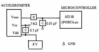
Schematic of Accelerometer Circuit
Our second task was to wire the hardware for the MIDI signals. Since the MIDI message is an asynchronous serial communication transmitted at 31250 baud rate, we found out that we can use the USART on the Mega32. We ordered a spliced DIN5 MIDI cable from allelectronics.com and wired the cable to our Mega32 custom PC board with the recommended configuration for MIDI OUT from the MIDI Manufacturers Association. Two port pins on the DIN5 cable are not used. The MIDI OUT DIN5 male end will be connected to the MIDI IN of the Roland RS-70 Keyboard.
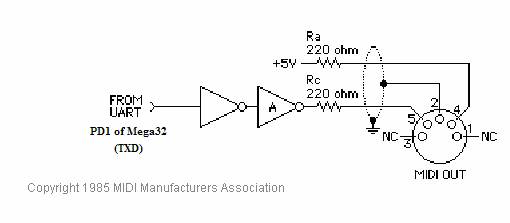
Schematic of MIDI OUT Circuit
Our final task was to integrate all our hardware and software together.
Home | Introduction | Design | Hardware | Software | Results & Conclusions | Appendix
Copyright @2005 Siew Im & Zheshen