I. Program Details
A. Understanding IR Encoding
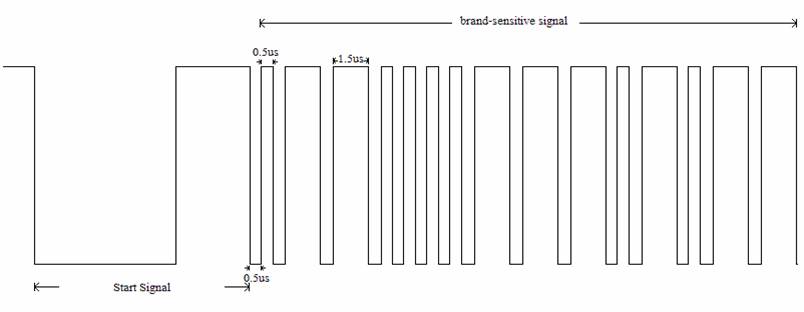
We spent a significant amount of time on the oscilloscope reverse engineering how the opcodes are encoded in IR. We have found from sending the signal and then pausing it on the oscilloscope over and over again that those remotes which follow the pulse-coded format use a similar encoding format. It begins with a start signal followed by a brand-sensitive code which appears in all button presses of a single remote. The brand sensitive code is a combination of short 0.5 microsecond and 1.5 microsecond pulses.
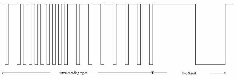
After the brand-sensitive coding comes the code unique to each button press. Like the brand sensitive coding, this is also a combination of long and short pulses. This segment is a total of 50*0.5 = 25 milliseconds with a total of 33*0.5 = 16.5 milliseconds at a voltage of 5V. This coding is followed by a stop code that resembles the pattern of the start signal but instead of a longer pulse of 0 volt followed by a shorter pulse of 5 volts, it is a longer pulse of 5 volts followed by a shorter pulse of 0 volt. When no button is pressed, the voltage remains at 5 volts. If a button is held down or is pressed too rapidly, a degenerate signal of only the start and stop encoding are sent.
B. IR receiving and decoding
There were four things that were particularly tricky. The first was how to sample the signal. The second was to determine an efficient way to store and to check the sampled signal without running out of memory. The third was to see what we have sampled in its entirety without facing the constraint of timing (i.e. how to freeze frame what we sampled). The fourth was to account for rapid button presses— the degenerate signal sent off by the remote--that do not code for anything.
As mentioned earlier, we picked a sampling rate of 0.1 msec because the smallest pulse is 0.5 msec. After several failed attempts, we finally successfully implemented a state machine that would be triggered by a high to low voltage transitions upon a button press. For the second problem, we picked an integer array of 128, a number much greater than the number of voltage changes from start to stop of the signal. Instead of recording all the samples of 5V as ones and 0V as zeros, we store the sum (or count) of our samples of ones upon detecting a zero voltage. This works for two reasons: 1) the voltage remains high when no button is pressed; 2) we do not start counting until a button is pressed. For the third problem, we addressed this issue by using the RS232. However, this seemed to pose some problems at first. There is a huge delay in displaying the real time sampling to HyperTerminal. At first we suspected that this was a matter of not sampling correctly or that the MCU was not quick enough for the signal. However, both suspicions were dispelled almost immediately. We resolved the problem by displaying the entire array only after the sampling is complete. And instead of using a FOR loop we used an incrementing index to display a sample at every interrupt call. While the numbers are being displayed, the sampling is turned off. This delay partially corrects our fourth issue by hindering rapid button presses. However, it does not address the issue of holding a button down. So we came up with a solution and that is to trigger the sampling only when a button is pressed and that we detect a sample of 42 +/- 1, which represents the first long stretch of 5Vs after the initial long stretch of 0Vs. After several tests, we realize we could shrink our integer array size to 34 but we arbitrarily set it to 70 just to account for any error in sampling.
Now in order to make what we have sampled useful, we need to store it in a 32-bit Long or a 16-bit Integer. We realized very quickly we could throw away the initial number and the last number as they represent start and stop so we only need to process 32 elements in the array. We also realized that samples less than a count of 5 (corresponding to short pulses) can be represented as a binary 0 and samples larger than or equal to 15 (corresponding to large pulses) can be represented as a binary 1. We also realized that the first 16 samples after the start sample is brand sensitive and because we do not need a brand sensitive remote, we also remove those bits. So we store only the 16 samples in binary 1s and 0s in a 16-bit integer. And we use the integer to match which button has been pressed.
Because we are not accounting for the brand sensitiveness of the remote, we are taking a slight risk in that two remotes may share the same second 16-bits unique to each button. The chance is small as most remotes have less than 40 buttons and there are 216 combinations for op codes. However, to account for this risk we made our receivers programmable. If two remotes share the same op code for a button, we could use another button to perform the same task on one of the two remotes.
See Appendix for op codes for the remote and a numerical example.
C. Connect Four Video Game
The code for the video game is based on Professor Land’s base code displaying a bouncing ball on the TV. All video game code for Connect 4 is performed during the vertical blanking period with the exception of two times for clearing the screen when a match of four has been achieved by one of the players. Screen clearing is done through multiple frames by drawing a black line for each frame, resulting in a visual effect of an Etch A Sketch screen clear (leaving us with a clean slate, or tabula rasa).
The game board on TV consists of a grid that is 8 x 9, which is a little larger than normal for increased game play and also for maximum remote control button usage. Right above the grid, each column is labeled with the numbers 1 through 9. Above the number labels, in the upper left corner is the text “CONNECT 4” and in the upper right “PLAYER 1” OR “PLAYER 2” depending on which player has the current turn. A char array of the same dimensions as the grid on screen is used to keep track of the board dynamics. In the array, a 0 refers to an empty slot, a 1 refers to the chip of player 1, and a 2 refers to the chip of player 2. The game begins with the entire grid array filled with zeros.
When the game first loads, player 1 begins. We keep track of turn in a variable named 'player', which begins with 1. When the IR decoder MCU communicates through Port C to the video game MCU the number of the button that was pressed on the remote, a quick FOR loop searches through the grid array in that column for the next available empty slot (the next empty row in the grid), and draws the chip for that player. At this point the variable 'player' is updated to indicate the turn of the next player, and the player text on screen is updated as well.
The next step in the algorithm for the video code is the portion that checks for any matches (4 in a row) that may have occurred as a result of the chip that was just placed. This is done by checking for four general directions: upper left to lower right, upper right to lower left, left to right, and down. In other words, the algorithm checks for each opposite direction together, since a connection of four can occur when a chip bridges two sides together. The only exception to that is the downward direction, since opposite to that is the upward direction in which there cannot possibly be any chips in relation to the chip that is last dropped. The checking algorithm in essence counts how many matching chips exist consecutively in a certain direction, and then counts the same way for the opposite direction, and then adds the two counted numbers together to detect a consecutive match of four.
All the aforementioned code is enclosed in an IF statement that is run if a variable called “win” is equal to 0, referring to the fact that no player has won yet. In the ELSE case (when win equals 1) we have the code for clearing the screen, for displaying the words “PLAYER X WINS,” and for redrawing the board for the next game. The variable win is set to one when a match of 4 consecutive chips is found by the previous algorithm. The erasing of the screen is accomplished by an INT variable called 'erasescreen'. Once variable win becomes 1, 'erasescreen' gets incremented during each frame. If 'erasescreen' equals to a number between 0 and 126, vertical black lines are drawn through the entire height of the screen where 'erasescreen' is the x coordinate of each line. When 'erasescreen' equals 127, or when the entire screen has been erased, the winner indication text is displayed. Then, if 'erasescreen' equals a number between 300 and 426 (starting from 300 to provide some time for the text to delay on screen), the screen is once again erased in the same way as the first time. When 'erasescreen' equals 476, the game is reinitialized, win is set back to 0, 'erasescreen' reinitialized, and the losing player gets to start the next game first (rule chosen arbitrarily), so the corresponding player text is displayed.
D. Interfacing the Two MCUs
It is worth mentioning that a “mutual de-bouncing” algorithm is used between the two MCU’s. Since there needs to be a way for the IR decoder MCU to turn off the Port C button indication signal, or else at every TV frame the algorithm will think that the same button is continuously pressed. Our solution is to use an indicator pin, pin A.0, as a means for the video game MCU to indicate to the IR decoder MCU that it has received the button number. On receiving the pin A.0 indication, the IR decoder MCU will then turn off Port C (set to 0x00), and on receiving a 0x00 at Port C, the video game MCU will then turn off pin A.0 to signal that it is ready for the next button push transmission.
II. Hardware Details
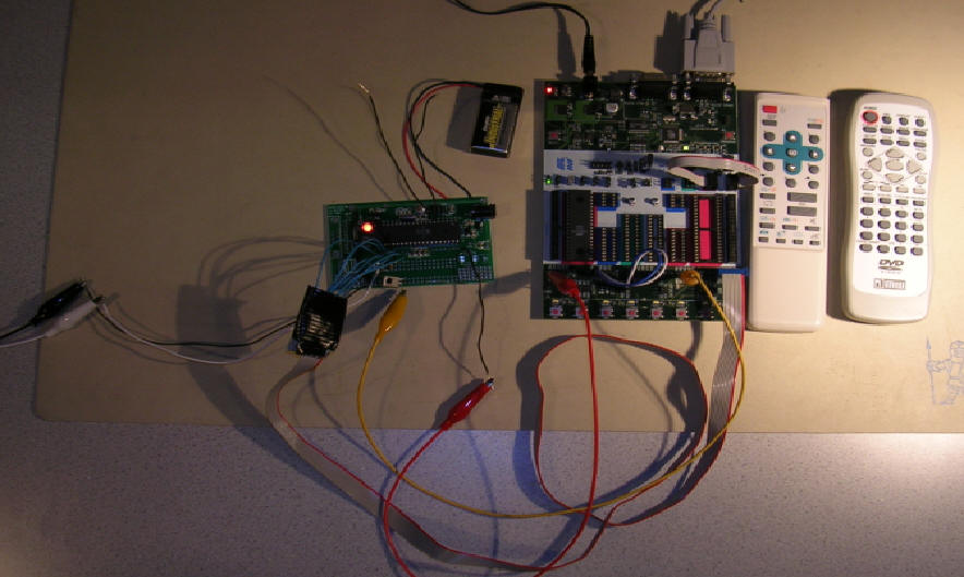
Someone who has both our video game source code and our IR receiver / decoder source code can easily duplicate the two Atmel Mega32 chips we are using, provided they have the resources to program the chips. That individual can also easily acquire the IR receiver at 38 MHz (part number 425-1120-ND) from Digikey and a few resistors as shown in the schematic. Following that same diagram, he or she can duplicate the hardware that we have created.
We were persistent in making everything we tried work.
III. Design and Code Reference
We referenced the RS232 code provided to us in Lab 3 by Professor Land. We also utilized the video code in Lab 4 by Professor Land. Otherwise, everything else we wrote was our own work.