The purpose of this project was to take a traditional remote controlled car and create our own control mechanisms. To control the car, we used a dual-axis accelerometer and LEDs (light emitting diodes) configured as photo-detectors. The control mechanism was selected using a single pole dual throw (spdt) switch was wired in a single pole single throw (spst) configuration. The two-axis accelerometer was used as a tilt sensor that detected how far the chip was angled from its neutral, flat position. An analog voltage was produced for both the x- and y-axes that corresponded to how far the accelerometer was tilted, and in what direction.
A custom LED array was also used to control the car. Though LEDs are traditionally thought of as light producing elements, they also produce a voltage corresponding to how much light they receive – brighter environments produce a greater voltage across the LED. We took advantage of this fact by causing the decrease in voltage by blocking light from entering one of the four LEDs (forward, reverse, left and right) to cause the car to move in the appropriate direction (See accelerometer & led sensor array unit).
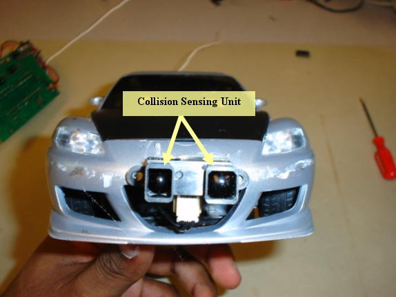
To implement a safer car, an infrared distance sensor was used to continually scan the area in front of the car. The sensor produced an analog output voltage proportional to how close an object was. When an object was detected, the car momentarily reverses to avoid a collision.
We chose this project because of our love of cars and the hardware aspect of gadgets. We thought that it would be a novel idea to be able to control the car with one hand by using the dual-axis accelerometer. To provide a contrast to this one-handed approach, we also decided to implement a spin on the traditional two-handed control of the car by using LEDs as photo-detectors. While the use of LEDs would still require two hands, the cost would be even less than the two joystick control scheme that the car came with. We wanted to implement both control schemes, then compare and contrast them at the end.
Figure 1: High Level Block Diagram
Figure 1 is a high level overview of our project. This is a very simplified version of the project but gives a general understanding of the main components within the system. For a more detailed analysis see (Hardware & Software Description). The components are used as follows:
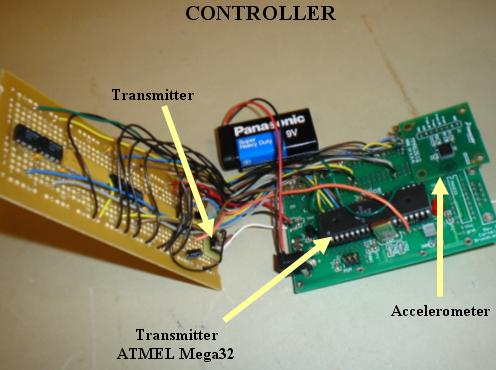
1) The MMA6261Q accelerometer drives the car based on how the control unit is tilted by the operator.
Ø Forward tilt – drives the car forward
Ø Backward tilt – puts the car in reverse
Ø Leftward tilt – makes the car turn left
Ø Rightward tilt – make the car turn right
Ø No tilt – the car does not move
The drive motor and steering motor can be operated simultaneously.
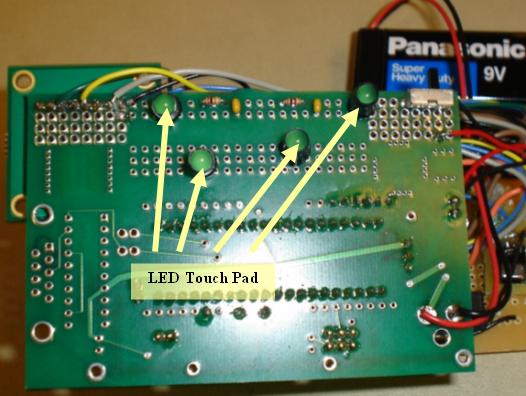
2) The LED sensor array provides an alternate control mechanism by allowing the operator to drive the car by touching one or two of the four LEDs that correspond to forward motion, reverse motion, left turn and right turn.
3) The ADC (analog to digital converter) unit on the Transmitter Mega32 takes the analog voltages from both the tilt sensor and LED touch pad and converts them to a digital number between 0 and 255. The software is calibrated to produce the desired action when a certain value of the ADC output is crossed.
4) The Transmitter Mega32 contains the transfer protocol software which uses the data provided by the ADC to operate the car. The data from it is processed before being sent to the transmitter using the Universal Synchronous and Asynchronous serial Receiver and Transmitter (USART) protocol.
5) The transmitter (RCT-433) takes the information provided by the Transmitter Mega32 and transmits it at 433.92 MHz. The FCC states that any low power non licensed transmitter must not cause interfere with licensed transmitters. The frequency of the transmitter is in the acceptable range of frequencies as listed in Part 15 of the FCC rules. The transmitter used less than 1 milliamp of current when transmitting a logical 0, and about 4.5 milliamps of current when transmitting a logical 1. Because the transmitter transmits a 1 when no signal is inputted, an inverter was used for the input to the transmitter to save power. We do not have to obtain FCC equipment authorization for the circuit that we are building because less than 5 of these circuits will be made and we do not plan on selling them.
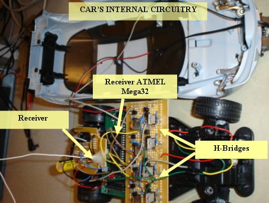
6) The receiver (RCR-433), located on the car itself, receives the transmitted signal. The signal has to be inverted to reverse the effects of the inverter on the transmitter end.
7) The IR Sensor detects how far objects are from the front of the car. The unit sends infrared pulses and determines distance by measuring the angle of the beam that returns. A pulse that is reflected from an object that is further away will have a greater angle from the plane of the reflector than an object that is nearby, see Figure 2.
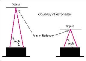
Figure 2: Distance calculation through triangulation
8) This ADC (analog to digital converter) converts the signal from the IR sensor into a number in the range of 0-255 to be interpreted by the Receiver Mega32.
9) The Receiver Mega32 contains most of the software for this project. It takes the information that is received, decodes it, checks the output of the digitally converted signal from the IR sensor, and then provides the correct signals to the h-bridges that control the drive motor and the steering servo.
10, 11) The information from the Receiver Mega32 is interpreted as drive forward, reverse, steer left or steer right. The forward and reverse instructions are sent to one h-bridge circuit which is connected to the drive motor of the car. The steering instructions are sent to another h-bridge circuit that is connected to the steering servo motor. A schematic of the H-Bridge and the components used is shown in Figure 11 in the Hardware Design section.
12) The speaker used in this lab emits a sound when the IR sensor senses an object in front of the vehicle when the user attempts to drive forward.
13, 14) The drive motor and steering servo were part of the original car. They both operated at 5V.
HARDWARE
DESIGN
Most of the time spent on this project was in designing and building the car’s circuitry. The car was gutted except for the chassis, drive motor and steering servo. Even the battery box was modified to accept 9V batteries. The transmitter controls that came with the car were replaced with our custom made controllers. The hardware components for this project were built and grouped accordingly:
· Accelerometer and LED Sensor Array
ACCELEROMETER & LED SENSOR ARRAY UNIT
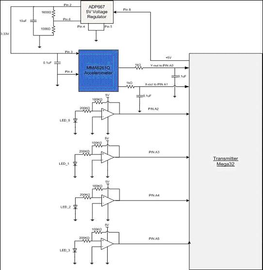
Figure 3: Accelerometer and LED sensor array schematic
Freescale MMA6261Q Dual-Axis Accelerometer:
The accelerometer (MMA6261Q) was generously donated to us by Freescale Semiconductor. This unit produced an analog voltage output corresponding to the amount of rotation in the x- or y-plane (the z-axis is referenced vertically). Contained within the device was a surface micromachined capacitive sensing cell. Acceleration along an axis caused a plate to slide, changing the capacitances between the plates (see Figure 4). This change was converted into an analog voltage.
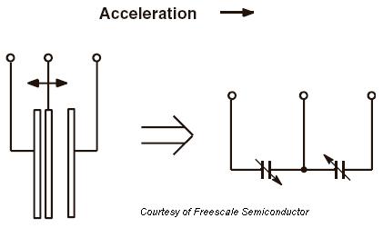
Figure 4: Simplified model of tilt sensor
When no tilt was applied in either direction the output voltages of both the x-axis and y-axis was approximately 1.65V. Tilting the sensor forward or backward up to -1g or +1g caused an output voltage between 0.85V and 2.45V, respectively, on the y-axis output line. Tilting the sensor left or right up to -1g or +1g causes an output voltage between 0.85V and 2.45V, respectively, on the x-axis line. These analog voltages were used to determine the threshold conditions at which the commands to operate the car forward, reverse, left, and right were set. We built an RC low-pass filter using a 1 kΩ resistor and a 0.1 μF capacitor (see Figure 5) to filter the outputs of the accelerometer before entering the Transmitter Mega32. This minimized clock noise from the switched capacitor circuit inside the device.

Figure 5: Accelerometer output low pass filter
ADP667 Voltage Regulator:
An additional voltage regulator was needed because the accelerometer chip required a voltage of 3.3V, not the 5V that was available on the board. We were able to produce a voltage of 3.3V using an ADP667 5V regulator graciously donated to us by Analog Devices. This chip allowed us to step down the 5V available on the prototype boards by creating the circuit in Figure 6. The values of the resistors were chosen using Equation. 1. VSET = 1.255V (Pin 6), R1 = 1000Ω, R2 = 1600Ω and VOUT was the final output.

Figure 6: Circuit used to produce 3.3V
![]()
Equation 1: Producing proper output voltage
4-Button Sensor Array:
This circuit was created using 4 LEDs. The LEDs that were available to us in the lab were yellow, red and green. Through experimentation, we found that green LEDs produced the highest voltages across the terminals from ambient light, and also had the largest voltage decrease when covered, which were desirable characteristics for our application. Through further experimentation, we found that covering the sides of the LEDs with opaque tape while leaving the top exposed produced a greater voltage change when covered up. The voltage change from the LED was small therefore amplification was used to magnify the change for more foolproof detection. To accomplish this, each LED was connected to an LM7111 op-amp in a non-inverting configuration (Fig. 7), which amplified the signal voltage by a gain of Av (see Equation 2)
.
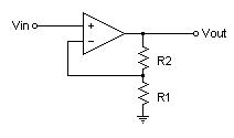
Figure 7: Non-inverting op-amp configuration
![]()
Equation 2: Non-inverting op-amp gain equation
This was enough to increase the voltage change while remaining within a maximum of 2.56V, which was the value of the internal voltage reference used by the ADC. The op-amp output for each of the LEDs (LED0 to LED3) was connected to ADC pins on the Transmitter (i.e. Pin A2 to A5). A delay was necessary between successive conversions because each ADC conversion value could take up to 125 microseconds to stabilize. We chose a delay of 1 millisecond to be safe which was still fast enough for our purposes. Each LED controlled specific functions of the car as follows: LED0 moved the car forward; LED1 moved the car backwards; LED2 turned the car left; and LED3 turned the car right. Because it was possible to press both forward the reverse LEDs or both left and right LEDs, code was specifically written to stop the car or drive the car straight, respectively, in these situations.
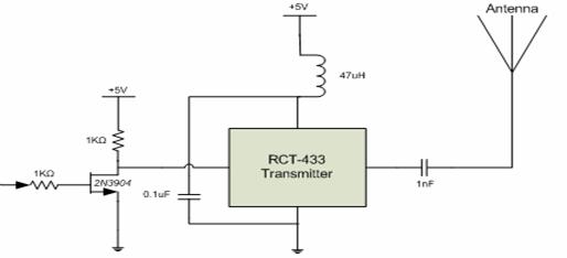
Figure 8: Transmitter schematic
The Transmitter Unit’s circuitry in Figure 8 was essential in sending the wireless signal to the remote controlled car. The transmitter used on/off keying (OOK), where the transmitter sends a logic 1 to transmit a logic one, and turns off to transmit a logic 0. The serial output from PortD.1 of the microcontroller (see Transmitter Software) was first inverted. This was done because the transmitter naturally sends a logic one when no data was inputted, which consumes more power than when the transmitter transmits a logic zero. Since the amount of time that data was being sent was very small, the inverter was used to save power. The inverted signal was then sent to the RCT-433 Transmitter where the signal was radiated through the 18cm antenna. An antenna of 18cm was used because the optimal antenna length was one-fourth of the signal wavelength. A 47 uH inductor was used between the power supply and the transmitter unit to prevent the RF energy from shunting to the power rail, which was an AC ground. A 1 nF capacitor was used between the transmitter and the antenna to prevent detuning of the signal.
The Wireless Protocol written by Meghan Desai was used to transmit data. This was a very convenient protocol to use because the transmitted and received functions were laid out for us. We found some errors in the ‘txrx.c’ driver file that had to be corrected before use. We also had to make some other slight modifications because we chose to use a baud rate of 1200 bps, which required setting both UBRRL and UBRRH. Even when using a lower baud rate led to less dropped packets, it did not totally eliminate the problem. To further solve this, we decided to send packets of information 5 times a second, so that even if a packet was dropped or corrupted, a new packet would be sent shortly thereafter.
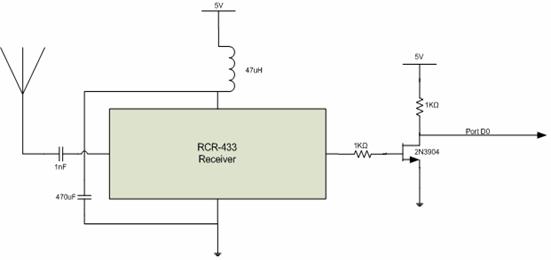
Figure 9: Receiver Schematic
The Receiver Unit’s circuitry in Figure 9 was attached to
the remote controlled car. The RCR-433 receiver was matched to the RCT-433 transmitter that we were
using. The 1 nF capacitor between the antenna and the receiver
unit prevented detuning of the signal.
The 47 uH inductor between the power supply
rail and the receiver unit prevented the RF signal from shunting to the power
rail, which was an AC ground. The
received signal was then inverted to reverse the effects of the inverter on the
transmitter side. The signal was then
sent to PortD.0 of the microcontroller, which was the USART receive port.
The Sharp GP2Y0A02 IR distance sensor operates by transmitting infrared signals and measuring the angle of the beam that returns in relation to the plane of the sensor (see Figure 2). The sensor was mounted to the front bumper of the car and tilted slightly upward to eliminate false readings from ground reflections. The sensor was an analog device that outputted a voltage proportional to how close an object was to the car (see Figure 10). Though the output became erroneous below 15 cm, we did not notice any adverse effects in our testing.
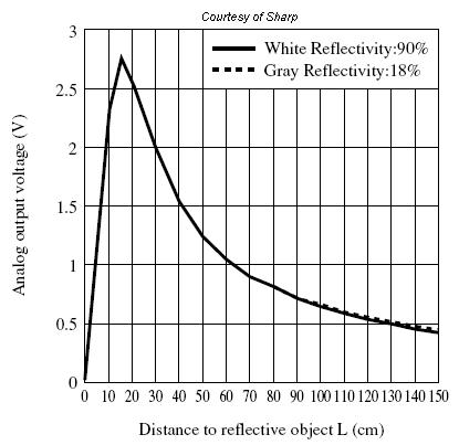
Figure 10: IR sensor output voltage vs. distance
The output of the distance sensor was fed into PortA.0 of the ADC on the Receiver Mega32. Whenever an object came closer than 24”, a signal was sent to the speaker to emit a tone. The car was then instructed to reverse briefly. Merely telling the car to stop was not suitable because of the car’s speed its momentum would still allow its collision.
We had initially tried using a Sharp GP2D12 IR sensor because it was a
surplus item that
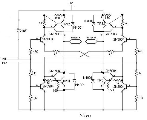
Figure 11: Schematic of H-Bridge
Since the
port pins of the microcontroller cannot supply enough current, an external
h-bridge circuit had to be used to drive the motor and servo as in Figure
11. This design was based on the circuit
found on bobblick’s website. The main components of the circuit were the
|
IN1 |
IN2 |
MotorA - MotorB |
|
0 |
0 |
Float |
|
0 |
1 |
Negative |
|
1 |
0 |
Positive |
|
1 |
1 |
Lock |
Table 1: H-bridge input/output logic
table
We had initially sampled LMD18200 h-bridges from National Semiconductor, but were not able to use them because they required a voltage supply between 12-55 V, which was difficult to achieve using batteries.
The software for this project was relatively easy to make. The data packet was coded in the following manner:
|
Bit0 |
Forward |
|
Bit1 |
Reverse |
|
Bit2 |
Stop |
|
Bit3 |
Left |
|
Bit4 |
Right |
|
Bit5 |
Straight |
|
Bit6 |
Unused |
|
Bit7 |
Unused |
|
Bit8 |
Unused |
Table 2: Bit encoding_________________
We chose to use this scheme because it enabled simple encoding and decoding protocols through masking. Care had to be taken in coding the collision algorithm because we wanted the car to reverse for only a short duration of time to avoid the objects in its path, but not too long that the car became out of control. We also forced the car to stop after 1 second of not receiving data to prevent it from continuing to operate whenever it became out of the range of the transmitter unit.
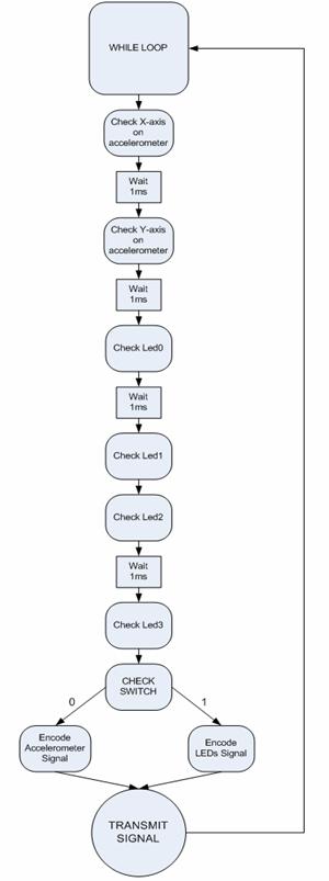
Figure 12: Flowchart of transmit software
RECEIVE SOFTWARE

Figure 13: Flowchart of receive software
The car was able to operate reliably. We found that even when the transmitter and receiver pair was close to each other, packets were dropped. This became a problem in a project such as ours because fast reactions were necessary. The controller must operate the car in a very deliberate manner to produce the right reactions from the car. Because there was some lag between the controller and the car, the operator must be aware of how to operate the car using this out control mechanism.
The IR sensor that was attached to the front of the car had a fairly small side-to-side range of detection. This meant that incoming objects must be close to the centerline of the car to be detected. When operating the car in real world conditions, this means that not all collisions can be avoided. This could have been remedied by having two additional sensors at both sides of the car, but that would have caused us drastically go over our $50 budget.
The accelerometer was more reliable method to control the car than LEDs. The LEDs were heavily dependant on the amount of ambient light that was available, which can vary widely. The amount of voltage that was produced by the LEDs varied between different colors. This would mean that any mass produced system using LEDs in this manner would have to be individually calibrated, which would negate the low costs of using LEDs. Eliminating LED controls would have reduced the size of the transmitter unit by over 50%.
We have conducted an endurance test with extra batteries and found out that the car could operate for 30 to 45 minutes of continued use. We believed this was on par with the original specifications of the car. Instead of six AA batteries, the car only required two 9V batteries. This resulted in the car operating faster than it originally was, because we are supplying approximately 7.5V to the motors. The effects were dramatic whenever the batteries are exhausted, as the car slowed to a crawl. The transmitter unit optimized power most effectively and was able to sustain the use of its battery better than the car itself.
We were able to keep the car’s design unaltered, except for the collision sensor attached to the front bumper. This was one of the goals for this project. The h-bridge circuit occupied most of the car’s internal circuitry. Had we been able to use an h-bridge chip, the size of the internal circuitry within the car would have drastically been reduced.
RF interference was a concern throughout the testing stages of this project because there were a few other teams using the same transmitter/receiver pair that operated at the same frequency as ours. In order to properly test the functionality of our car we the ECE lounge to eliminate the possibility of interference. Testing the car in the ECE lounge allowed us to very that the range of operation between the car and controller was 30 feet.
We are extremely satisfied with how the project turned out. We were able to successfully implement both accelerometer and LED sensor controls. As expected, the accelerometer was a better control mechanism than the LEDs. To improve the LED controls in the future, we could possibly have another LED to be used solely to calibrate the ambient light threshold wherever the car is being operated. This would adjust to changing light conditions for a more robust control system.
The Mega32 chip was more powerful than we needed. Because the speed and processing power required for this project was not stringent, we used approximately 55% of the chip’s functionalities.
We made use of the Wireless Protocol by Meghan Desai. This greatly simplified the transfer/receiver procedure. However, we had to correct some errors in the driver file before it would operate. We also made use of the receiver box to make sure that we had wired up the transmitter correctly.
We were able to come in just under budget (see APPENDIX-C). Most of the main components for this project we bought and had already owned (i.e. the remote controlled car). Whatever components that were essential to the project and which was too costly towards our budget, we built (i.e. the h-bridges).
1. To accept
responsibility in making decisions consistent with the safety, health and
welfare of the public, and to disclose promptly factors that might endanger the
public or the environment;
We chose to implement the collision sensor to make the car even safer to use. Because the car runs at a higher speed than stock, we felt that this was a necessary addition.
2. To avoid real or perceived
conflicts of interest whenever possible, and to disclose them to affected
parties when they do exist;
There were not many sources of conflict during the course of this
project. We coordinated with the other
groups that were using transmitters and receivers to have different testing
time slots to avoid interference.
3. To be honest and realistic in stating
claims or estimates based on available data;
All of the circuit diagrams and descriptions are accurate to the fullest
extent of our knowledge.
4. To reject bribery in all its forms;
We did not encounter any opportunities for bribery, nor would we have
accepted these offers had they arisen.
5. To improve
the understanding of technology, its appropriate application, and potential
consequences;
We learned a great deal through this lab, especially about h-bridges and the
subtleties of using wireless transmission.
6. To maintain
and improve our technical competence and to undertake technological tasks for
others only if qualified by training or experience, or after full disclosure of
pertinent limitations;
We did not work on any other team’s projects, and whenever we had questions
we were quick to ask
7. To seek,
accept, and offer honest criticism of technical work, to acknowledge and
correct errors, and to credit properly the contributions of others;
We consulted with
8. To treat fairly all persons regardless
of such factors as race, religion, gender, disability, age, or national origin;
We are a multicultural project team so this wasn’t an issue.
9. To avoid injuring others, their
property, reputation, or employment by false or malicious action;
We added the collision sensor to make the car safer to operate. We tested the car in the ECE lounge when no
one was present to avoid injuring others.
We are not trying to sell this project.
10. To assist colleagues and co-workers
in their professional development and to support them in following this code of
ethics.
We did not observe breeches of the code of ethics, so we did not have to enforce these policies.
Contained here is a complete listing of the commented code used for this project. It contains both the transmitter and receiver codes as well. Most of the software was written in C with not much use of Assembler.
************************************************************************
************************TRANSMITTER
SOFTWARE*********************
************************************************************************
#include <Mega32.h>
#include <stdio.h>
#include<.\txrx.c>
#define begin {
#define end }
#define t1 200 //0.5sec (prescalar
64) for button presses
#define delay 1 //1ms delay for a/d converter
#define data_length
1
#define tx_id
3
char data[data_length];
unsigned char txtime;
unsigned char adtime;
unsigned char Ain; //holds value
of A/D conversion
unsigned char xaxis, yaxis, fwd, rev, left,
right;
unsigned char selector;
unsigned char led;
void initialize(void); //set the mcu
up
void datatrans(void);
//timer0
compare match ISR
interrupt [TIM0_COMP] void
tim0comp(void)
begin
if (txtime>0)
--txtime; //decrement
the time(s) if not already 0
if (adtime>0)
--adtime;
end
void main(void)
begin
initialize();
while(1)
begin
//x-axis accelerometer (fwd/rev)
Ain = ADCH;
if (Ain<115) xaxis=0x02; //tilt rev
else if (Ain>185)
xaxis=0x01; //tilt fwd
else xaxis=0x04;
//y-axis accelerometer (left/right)
ADMUX=0b11100001;
ADCSR.6=1;
adtime=delay;
while(adtime>0)
{};
Ain=ADCH;
if (Ain<115) yaxis=0x08; //tilt left
else if (Ain>185)
yaxis=0x10; //tilt right
else yaxis=0x20;
//fwd led
ADMUX=0b11100010;
ADCSR.6=1;
adtime=delay;
while(adtime>0)
{};
Ain=ADCH;
if (Ain<185)
begin
fwd=0x01;
PORTD.7=0;
end
else fwd=0x00;
//rev led
ADMUX=0b11100011;
ADCSR.6=1;
adtime=delay;
while(adtime>0)
{};
Ain=ADCH;
if (Ain<185)
begin
rev=0x02;
PORTD.7=1;
end
else rev=0x00;
//if fwd and rev leds
not covered, stop
if ((fwd==0) && (rev==0)) fwd=0x04; //stop
//if fwd and rev both covered, stop
if ((fwd>0) && (rev>0))
begin
fwd=0x04;
rev=0x00;
end
//left led
ADMUX=0b11100100;
ADCSR.6=1;
adtime=delay;
while(adtime>0)
{};
Ain=ADCH;
if (Ain<185)
begin
left=0x08;
end
else left=0x00;
//right led
ADMUX=0b11100101;
ADCSR.6=1;
adtime=delay;
while(adtime>0)
{};
Ain=ADCH;
if (Ain<185)
begin
right=0x10;
end
else right=0x00;
//if left and right leds not covered, straight
if ((left==0) && (right==0))
left=0x20; //stop
//if left and right both covered,
straight
if
((left>0) && (right>0))
begin
left=0x20;
right=0x00;
end
//start another conversion
ADMUX=0b11100000;
ADCSR.6=1;
adtime=delay;
while(adtime>0)
{};
if (txtime==0)
begin
datatrans();
tx_me(data,
data_length, tx_id);
end
end
end
void datatrans(void)
begin
txtime = t1;
selector=PINC.0; //state of selector switch
if
(selector==0)
begin
data[0]=xaxis|yaxis;
end
else
begin
data[0]=fwd|rev|left|right;
end
end
void initialize(void)
begin
DDRC.0=0;
//port c.0 is input (selector switch)
DDRD.7=1; //port d.7 is output (control led)
//set-up timer0
OCR0=249;
//1 ms
TIMSK=2;
//turn on timer0 compare match ISR
TCCR0=0b00001011; //prescalar
64, clear on match
//init the A to D converter
//channel zero/ left adj
/internal Aref (2.56V)
//!!!DISCONNECT Aref
jumper!!!!
ADMUX = 0b11100000;
//enable ADC and set prescaler
to 1/128*16MHz=125,000
//and clear interupt
enable
//and start a conversion
ADCSR = 0b11000111;
txtime =
t1;
txrx_init(1,0,3,64,0); //TX only, 1200 baud, led off
//crank up the ISRs
#asm
sei
#endasm
end
************************************************************************
************************************************************************
************************************************************************
**************************RECEIVER SOFTWARE**********************
************************************************************************
#include
<Mega32.h>
#include <stdio.h>
#include<.\txrx.c>
#define begin {
#define end }
#define MAX_RX_LENGTH 32
#define t1 1200
void initialize(void);
unsigned char my_rx_data[MAX_RX_LENGTH];
unsigned char k;
//individual
bits of incoming data
unsigned char bit0, bit1,
bit2, bit3, bit4, bit5, bit6, bit7;
unsigned char fwdrev1,
fwdrev2; //drive motor state
unsigned char leftright1,
leftright2; //steering
motor state
unsigned char
collision; //IR detector
state
unsigned char ain; //A/D input
from IR detector
unsigned char time2;
unsigned char count;
unsigned int
time1;
unsigned char data; //incoming data
//timer0
compare match ISR
interrupt [TIM0_COMP] void
tim0comp(void)
begin
//decrement the times if not already 0
if (time1>0) --time1;
if (time2>0) --time2;
end
void main(void)
begin
initialize();
while(1)
//main program loop
begin
ain=ADCH; //store A/D result
if (ain>70)
collision=1; //collision
detection
else collision=0;
ADCSR.6=1; //start another conversion
//collision=PINA.0;
if (collision) PORTD.7=0;
else PORTD.7=1;
if (rxdone()==1) //data received
begin
k=0;
init_getrx();
while(rx_empty()!=1)
begin
my_rx_data[k]
= get_next_rx_data();
k++;
end
data=my_rx_data[5];
bit0 = data&0x01;
bit1 = (data&0x02);
bit2 = (data&0x04);
bit3 = (data&0x08);
bit4 = (data&0x10);
bit5 = (data&0x20);
if (bit0==0x01) //fwd
begin
fwdrev1=1;
fwdrev2=0;
end
if (bit1==0x02) //rev
begin
fwdrev1=0;
fwdrev2=1;
end
if (bit2==0x04) //coast
begin
fwdrev1=0;
fwdrev2=0;
end
if (bit3==0x08) //left
begin
leftright1=1;
leftright2=0;
end
if (bit4==0x10) //right
begin
leftright1=0;
leftright2=1;
end
if (bit5==0x20) //straight
begin
leftright1=0;
leftright2=0;
end
//prevent forward progress is
collision imminent
if ((collision==1) &&
(fwdrev1==1))
begin
fwdrev2=1;
time2=500;
count=count++;
end
while ((time2>0) &&
(count<3))
begin
PORTD.6=1;
fwdrev1=0;
fwdrev2=1;
end
PORTD.6=0;
count=0;
PORTC.0=fwdrev1;
PORTC.1=fwdrev2;
PORTC.2=leftright1;
PORTC.3=leftright2;
rx_reset(MAX_RX_LENGTH);
time1=t1;
end
//if (rxdone ==1)
if (time1==0)
begin
PORTC.0=0;
PORTC.1=0;
PORTC.2=0;
PORTC.3=0;
end
end
//while
end //main
void initialize(void) //set everything up
begin
DDRD.6=1;
//pin6 of port d is output (speaker)
PORTD.6=0; //speaker off initially
DDRA.0=0;
//pina.0 input (collision sensor)
DDRD.7=1;
//pin7 of port d is output (led)
PORTD.7=1; //led off initially
//c.0=fwd/rev 1
//c.1=fwd/rev 2
//c.2=left/right 1
//c.3=left/right 2
DDRC=0xff; //portc is
output (h-bridges)
//set-up timer0
OCR0=249;
//1 ms
TIMSK=2;
//turn on timer0 compare match ISR
TCCR0=0b00001011; //prescalar
64, clear on match
//init the A to D converter
//channel zero/ left adj
/INTERNAL Aref
//!!!DISCONNECT Aref
jumper!!!!
ADMUX = 0b11100000;
//enable ADC and set prescaler to 1/128*16MHz=125,000
//clear interupt
enable, start a conversion
ADCSR = 0b11000111;
time1=0;
txrx_init(0,1,3,64,0); //RX only - 1200 baud - led off
rx_reset(MAX_RX_LENGTH);
//crank up the ISRs
#asm
sei
#endasm
end
************************************************************************
************************************************************************
The following figures show the schematics of the hardware for the handheld controller and the hardware that was built into the car.

Schematic of Hand Held Controller

Schematic of Car’s Internal Circuitry
|
Items |
Quantity |
Price (per
quantity) |
|
Atmel Mega32 |
2 |
$8.00 |
|
PC board (last year’s) |
2 |
$2.00 |
|
Solder board |
2 |
$2.50 |
|
Receiver (RCR-433) |
1 |
$4.00 |
|
Transmitter (RCT-433) |
1 |
$4.00 |
|
Sensor board w/ accelerometer (MMA6261Q) |
1 |
Donated |
|
IR sensor (Sharp GP2Y0A02 IR sensor) |
1 |
$12.50 |
|
Voltage regulator (Analog Devices ADP667) |
1 |
Sampled |
|
Radio controlled car |
1 |
Already owned |
|
9V battery |
3 |
Already owned |
|
LEDs, capacitors, resistors, inductors |
|
Lab supply |
|
TOTAL COST |
$45.50 |
|
This includes a list of the tasks carried out by each team member in this project. Working together was a goal of ours from the beginning so that each of us could get the best possible understanding of the components in our project.
Donn Kim (ddk26)
- Final Project Leader (knows a
lot about remote controlled cars)
- Hardware Guru design
- Soldering Wizardry
- Essential Research for Project
- Project Software Design
- Software Testing and Debugging
- Entire Project Testing and Debugging
- Moral Support & Commiseration
- Editor of Final Project Report
- Website Construction
Antonio
C. Dorset (acd32)
- Hardware Guru implementation
- Essential Project Research
- Project Software Design
- Software Testing and Debugging
- Entire Project Testing and Debugging
- Moral Support & Commiseration
- Writer of Final Project Report
- Website Construction
Here are some pictures of our project: