 Voice Recognition Robotic Car
  Voice Recognition Robotic Car
 By Andre Harison (avh8) Chirag Shah (css34)
Introduction High Level Design Software/Hardware Design Results Conclusion Appendix References Pictures
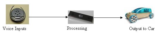
Think about a creating a car which would be controlled by your voice. By giving a command, the car would drive you to your destination. The voice recognition algorithm we used could be applied to daily life; for example it would be most helpful to disabled people to perform their daily work. We created a speech controlled car using various electrical and mechanical domains such as digital signal processing, analog circuit design, and interfacing the car with the Mega32.
back to top
We were both interested in building some kind of robot. We researched projects that had been done in the field of robotics and there existed a line follower robot, and sensor robots but none of them used speech to control a robot. In the digital world, it would be cool to make a robot which obeys human speech commands and performs errands. In the movie “I, Robot”, (where our project idea came from) they showed a high tech robotic car responding to vocal commands and driving according to human speech. We picked a part of the theme of the movie to make a car move using speech recognition. The required computation to process speech would normally overflow the mega32 memory, but we found a nice algorithm from a website by Tor Aamodt, from the ECE department at the University of British Columbia that would fit within our constraint.
Speech Analysis:
In order to analyze speech, we needed to look at the frequency content of the detected word. To do this we used several 4th order Chebyshev band pass filters. To create 4th order filters, we cascaded two second order filters using the following "Direct Form II Transposed" implementation of a difference equations.
Where the coefficient a’s and b’s were obtained through Matlab using the following commands.
[B,A] = cheby2(2,40,[Freq1, Freq2]);
(Where 2 defines a 4th order filter, 40 defines the stop band ripple in decibels, and Freq1 and Freq2 are the normalized cutoff frequencies).
[sos2, g2] = tf2sos (B2, A2,'up','inf');
Fingerprint Calculation:
Due to the limited memory space on the Mega32, we needed a way to encode the relevant information of the spoken word. The relevant information for each word was encoded in a “fingerprint”. To compare fingerprints we used the Euclidean distance formula between sampled word fingerprint and the stored fingerprints to find correct word.Euclidean distance formula is:
P = (
) and Q = (
)
Where P is a dictionary fingerprint and Q is the sampled word fingerprint and p i and q i are the data points that make up the fingerprint. To see if two words are the same we compute the Euclidean distance between them and the words with the minimum distance are considered to be the same. The formula above requires squaring the difference between the two points, but since we are using fixed point arithmetic, we found that squaring the difference produced too large of a number causing our variables to overflow. Thus we implemented a "pseudo Euclidean distance calculation" by moving the sum out of the square root reducing the equation to
D = ![]()
PWM duty cycle calculation:
The motors in the car were measured to have a 50 Hz PWM frequency and movement was controlled by varying the duty cycle from 5% to 10%. To generate the PWM signals we used timer/counter1 in phase correct mode. The top value of timer/counter 1 was set to be 20000 and using a /8 prescalar the PWM signal was set to have a frequency of 50Hz = 16MHz/(8*2*20000). To calculate the duty cycle the following equation was used OCR1x = (20000 - 40000*duty cycle). Where OCR1x is the value in the output compare register 1 A or B.
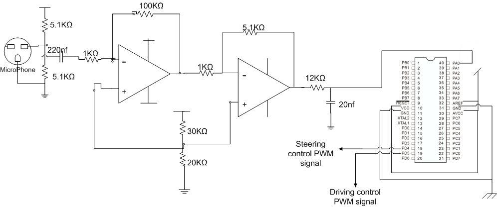
The signal coming out of the microphone needed to be amplified. We had two different versions of operational amplifier, LMC 711 and LM 358. The LMC711 has a slew rate of 0.015 V/μs, on the other hand LM 358 has 0.3V/μs. The LM358 has a better slew rate and it gave us better response to input signal, so we used it when we designed our amplification circuit.
The signal processing of speech requires lot of computations, which implies we need fast processor, but we had to operate at 16 MHz. In order to minimize the number of cycles we used filtering the audio signal we had to write most of the code in assembly. We wrote all of 10 digital filters in assembly which made them very efficient and significantly improved our performance over a C code implementation.
We believe that we did not have any standards regarding our project.
Tor's algorithm that we used is not patented so we do not have anything that has been copyrighted or patented by anyone to our knowledge.
back to top
The Basic algorithm of our code was to check the ADC input at a rate of 4 KHz. If the value of the ADC is greater than the threshold value it is interpreted as the beginning of a half a second long word. The sample word passes through 8 band pass filters and is converted into a fingerprint. The words to be matched are stored as fingerprints in a dictionary so that sampled word fingerprints can be compared against them later. Once a fingerprint is generated from a sample word it is compared against the dictionary fingerprints and using the modified Euclidean distance calculation finds the fingerprint in the dictionary that is the closest match. Based on the word that matched the best the program sends a PWM signal to the car to perform basic operations like left, right, go, stop, or reverse.
At start up as part of the initialization the program reads the ADC input using timercounter0 and accumulates its value 256 times. By interpreting the read in ADC value as a number between 1 to 1/256, in fixed point, and accumulating 256 times. The average value of ADC was calculated without doing a multiply or divide. Three average values are taken each with a 16.4msec delay between the samples. After receiving three average values, the threshold value is to be four times the value of the median number. The threshold value is useful to detect when a word has been spoken or not.
The program considers a word detected if a sample value from the ADC is greater than the threshold value. Every sample of ADC is typecast to an int and stored in a dummy variable Ain. The Ain value passes through 8 4th order Chebyshev band pass filters with a 40 dB stop band for 2000 samples (half a second) once a word has been detected. When a filter is used its output is squared and that value is accumulated with the previous squares of the filter output. After 125 samples the accumulated value is stored as a data point in the fingerprint of that word. The accumulator is then cleared and the process is begun again. After 2000 samples 16 points have been generated from each filter, thus every sampled word is divided up into 16 parts. Our code is based around using 10 filters and since each one outputs 16 data points every fingerprint is made up of 160 data points.
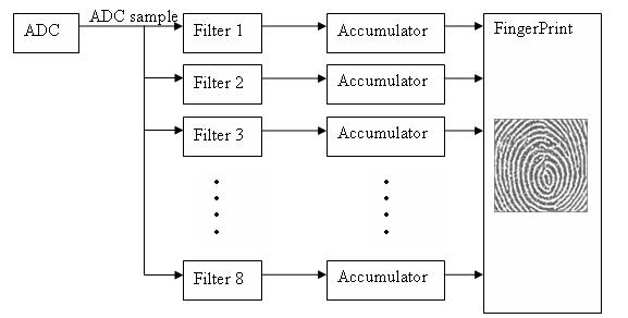
We chose a 4th order Chebyshev filter with 40 dB stop band since it had very sharp transitions after the cutoff frequency. We designed 10 filters a low pass with a cutoff of 200 Hz, a high pass with a cutoff of 1.8 KHz, and eight band passes that each had a 200 Hz bandwidth and were evenly distributed from 200Hz to 1.8 KHz. Thus we had band pass filters that went from 200-400 Hz, 400-600, 600 – 800 and so on all the way to the filter that covered 1.6 Khz – 1.8 Khz. We designed our filters in this way because we felt that most of the important frequency content in words was within the first 2 KHz since this usually contains the first and second speech formants, (resonant frequencies). This also allowed us to sample at 4 KHz and gave us almost enough time to implement 10 filters. We thought we needed ten filters each with approximately a 200 Hz bandwidth so that we would have enough frequency resolution to properly identify words. Originally we had 5 filters that spanned from 0 – 4 KHz and were sampling at 8 KHz, but this scheme did not produce consistent word recognition.
In order to implement 4th order Chebyshev filters, we cascaded 2 second order IIR filters in series to make 4 th order filter using Prof. Land's sample assembly code for 2 nd order IIR filters. We generated 4th order IIR filter coefficients using Matlab as described in the math section above. The coefficients though are floating point numbers and to convert them to fixed point we multiply the numbers by 256 and round it off to nearest integer instead of using the float2fix macro, which does not round. Fixed point was used versus floating point, which would have been more accurate because the Mega32 floating point calculations are very slow and we needed to call all our filters at a rate of 4 KHz, the sampling frequency.
The Mega32 only has 2 KiloBytes of RAM and a word sampled at 4 KHz for a half a second would require 2 Kilobytes of memory to store. In order to make a fingerprint then from a word we had to pass the ADC output through all the filters faster than the ADC sample time of 250µs. We also modified our filters slightly, by altering the gain coefficient, to have a maximum filter gain of 20 instead of 1. This was done to prevent the filter output from under flowing and going to zero when it was squared. The output of the filter was squared in order to store the intensity of the sound rather than just the amplitude. To reduce the time squaring the filter output took it was combined with the filter function and also the accumulation of the previous squared filter outputs was also put into assembly to reduce the cycle time. Nonetheless the reduction in cycle time was not enough to implement all 10 filters, so we stopped calling the high pass filter. Later on the low pass filter was removed because low frequency noise seemed to be interfering with the filter output.
Once the fingerprints are created and stored in the dictionary when a word was spoken, it was compared against the dictionary fingerprints. In order to do the comparison, we called a lookup() function. The lookup() function did a pseudo Euclidean distance formula by calculating the sum of the absolute value of the difference between each sample finger print a finger print from the dictionary. The dictionary has multiple words in it and the lookup went through all of them and picked the word with the smallest calculated number. We had originally used the square of the correct Euclidean distance calculation, d = Σ(pi – qi) 2. The words we finally used in our dictionary were Let's Go, (sound of a finger snapping), daiya [right – in Hindi], rukh [stop – in Hindi], peiche [back – in Hindi]. We had originally used English words, go, left, right, stop, and back, but many of these words seemed to be very similar in frequency as far as our algorithm was concerned. We then went to vowels and had better success, but we still wanted to use words that were directions and so we went to Hindi The set of words that we used were mostly orthogonal, but in Hindi left is baiya, which sound very similar to daiya and so that could not be used. We had previously had success with snapping so we used that for left.
Once a word is recognized, its time to perform an action based on the recognized word. To perform an action we generated a PWM signal using timercounter1. Control of the PWM signal generation is done by the carcontrol() function. For our car, we needed to generate two different PWM signals, one for moving the car front/back and another one to steer left or right. We also need to send a default PWM signal to pause a car. We chose timercounter1 because it has two different compare registers, OCR1A and OCR1B and can output two unique PWM signals. We used Phase correct mode to generate PWM signals because it is is glitch free, which is better for the motor.
To find out a frequency and a duty cycles at which car turns forward/backward and left/right, we attached an oscilloscope probe to a car’s receiver. We sent different signals to the receiver using the car’s remote control an d measured the frequency and duty cycle for different motions. From the measurements, we found that car PWM frequency was 50Hz (period of 20ms) and had the following properties.
Note: Most servo motors have period gap of 30ms between two signals. It for a pulse of 0.5ms to go in one direction and 2.5ms pulse to go in the other direction which is pretty close the duty cycle values we measured.
We used OCR1A to control forward/backward operation of a car and OCR1B to control left/right operation.
The microphone that we used has a built in amplifier but after checking through oscilloscope, the signal strength was pretty low. We built the above amplifier signal to improve the peak to peak audio signal. The op. Amps are in negative feed back loops and are inverting and thereby have a gain of
So the total gain of the circuit is
, with a dc bias of 2V given by the resistor divider circuit at the positive terminal of the op amp.
back to top
Since we had to pass the ADC output through all of the filters faster than our sample time; the time it took do all the filter calculations was very important. We were able to run through 9 filters in under 4000 cycles, which is the amount of cycles available when sampling from the ADC at 4 KHz. The fingerprint comparison function did not have a speed requirement and so the cycle time for that was unimportant. The program was able to recognize five words, but sometimes it would become confused and match the incorrect word if the word that was spoken varied too much from the word stored in the dictionary. As a rough estimate the program recognized the correct word about 70% of the time a valid word was spoken. The program achieved success using Chirags voice, and with sufficient practice a person could say the same word with a small enough variation for the program to recognize the spoken word most of the time. For the general person though the recognition program would have a much lower percentage of success. Also the words in the dictionary are words spoken by only one person. If someone else said the same words it is unlikely the program would recognize the correct word most of the time, if at all.
For safety an testing we made sure the PWM signals sent to the car were as close to neutral as possible, while still letting the move go forward and backward. We did this to prevent the car from going out of control and potentially hurting others. Our project did not use any RF signals and the board we used ran just off of a battery so there were no physical connections to anything involving other peoples projects. Also the only pins switching state were the pins for the PWM, which were mostly covered by wire.
back to top
At the beginning of our project, we set a goal to recognize five words, at the end of project we got five words to be recognized. However our five words needed to be orthogonal to each other because our filters were not giving a high enough resolution and inaccuracy in fingerprint calculations due to using fix point arithmetic made the lookup function to be error prone. As a result, we had to pick various different words that sound apart. If we had to do this again instead of trying to use the Euclidean distance formula to match words we would like to try do perform a correlation of the two fingerprints. A correlation is less sensitive to amplitude differences and is a better way of identifying patterns between two objects. If we had faster process chip, we could modified our algorithm to add more filters, perform Fourier transform, or floating point arithmetic in order to improve our results.
Intellectual property considerations:
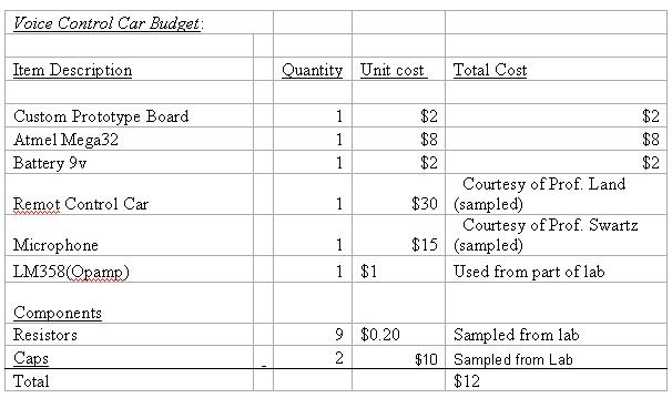
We did not have to sign any disclosure to receive sampled car and microphone.
We used Tor’s code as a reference to start our code in the end our code is quite different, though the overall algorithm is still the same.Ethical considerations:
- To accept responsibility in making engineering decisions that are consistent with the safety, health and welfare of the public, and to disclose promptly factors that might endanger the public or the environment.
Whenever we were testing our car, we ensured that the car would not bump into any one or damage anyone else's project. We always tested our car by putting it upside down so if any commands goes wrong and car goes unstable, it would not hurt anybody.- To avoid injuring others, their property, reputation, or employment by false or malicious action.
During our car test, we took steps to ensure safety of student group besides us and students who were watching our car test.
- To assist colleagues and co-workers in their professional development and to support them in following this code of ethics.
There was another group who was working speech recognition project, we try to be cooperative with them and discuss our ideas with them to solve each others problem. Also, there was another group who was working on video game generation and they had difficulty with output, we tried to help them solve their problem.- To improve the understanding of technology, its appropriate application, and potential consequences.
Our project used mega32 chip, which is not a powerful computation chip. Though our project required extensive amount of calculation but we were still able to fit into the chip. In order to make speech recognition more powerful and accurate, one could use a better powerful chip to do extensive calculation and accuracy. This project was based on DSP, initially we had basic knowledge about DSP; while working on this project, we learned a lot of about DSP.- To improve the understanding of technology, its appropriate application, and potential consequences.
We ensured that the car we were using was operated within the manufacture’s specification.- To maintain and improve our technical competence and to undertake technological tasks for others only if qualified by training or experience, or after full disclosure of pertinent limitations.
To make sure the power limits of the motors and chips stay within certain level. We were very careful about power supply of the car motors; PCB board stays within their specified level.
back to top
We both worked very hard as team on this project to accomplish our goals. In short there was no task that was done by one individual, the list of the tasks we did were create the noisemeasuremenut function, filter functions (1 - 10), lookup function, carcontrol function, pcb board construction, and car testing. We started this project over spring break and to understand the sample voice recognition algorithm from Tor’s website. We started implemented our speech algorithm based on his example and improved on it through out the semester.
References
Background Reference:
back to top4th Order filters Matlab Routine (calculates 4th order filter coefficients)
2nd order filters Matlab Routine (calculates 2nd order filter coefficients)
back to topPictures
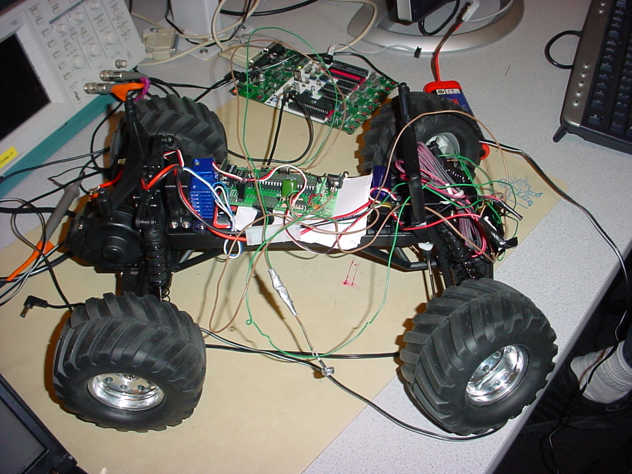
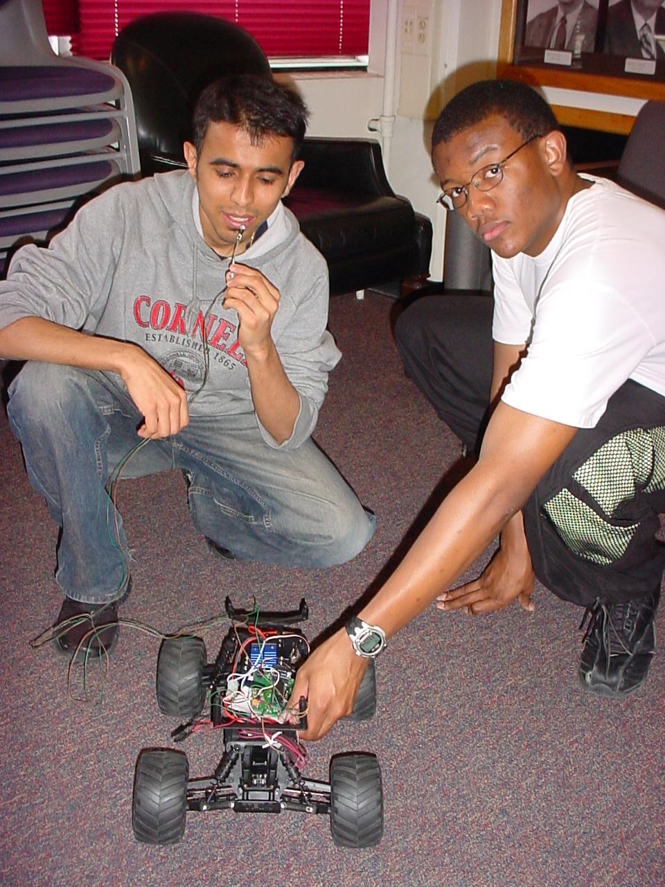
Robotic Car
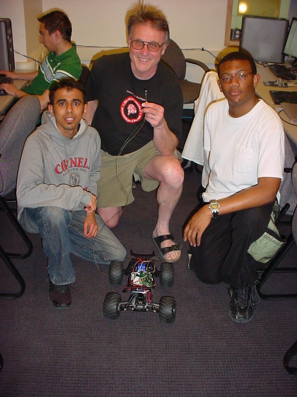
Group Picture
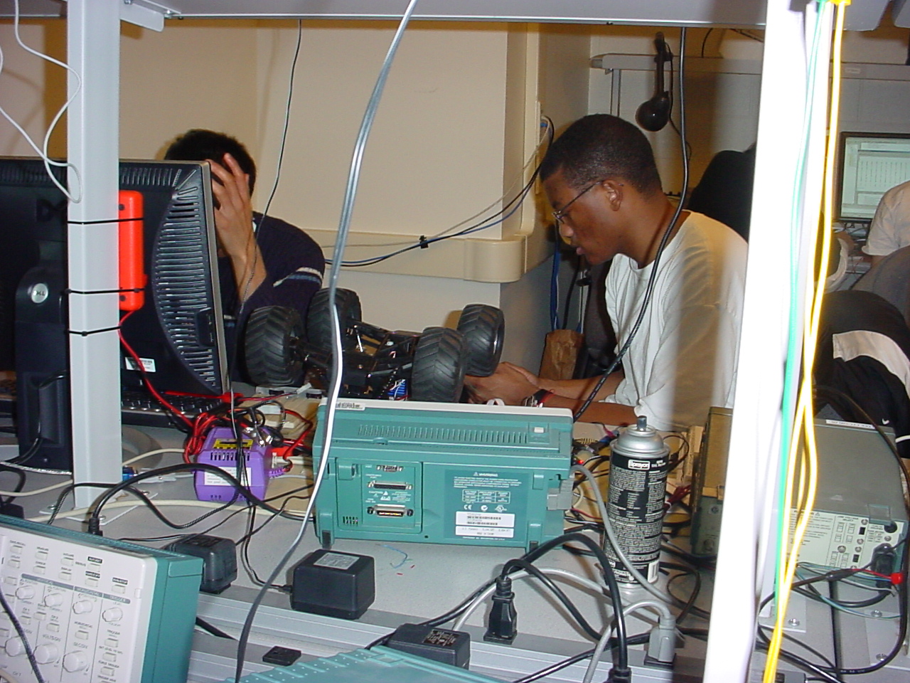
Deep Thought
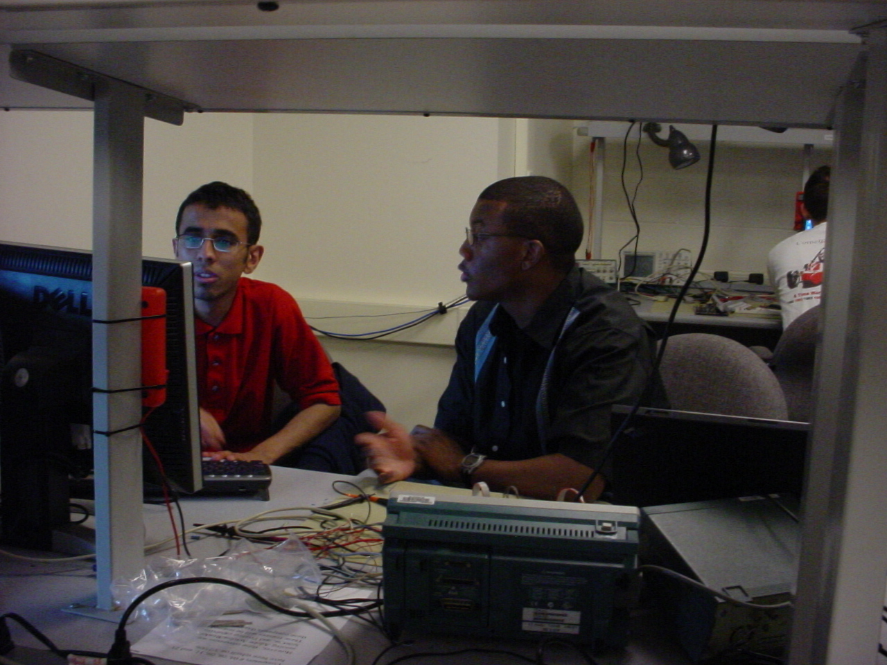
Discussion
Car Assembly
Frustration
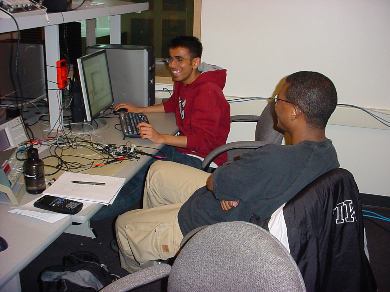
Accomplishment
Finally Demo!