Marcin Bojanczyk, Chris Danis and Brian Rogan
{mjb233,cgd3,bcr6}@cornell.edu
Introduction | [ top ] |
SecureLED is an optical access control device which replaces current RFID or Magnetic Strip technologies with a cryptographically secure, contact-less device which communicates over commodity Light Emitting Diodes (LEDs).
This project started with one central premise: current physical access control systems are insecure in fundamental ways. We sought a way to remedy this problem, and came accross recent work which demonstrated the potential of communicating over cheap commodity LEDs. We used these as the basis of our system, building on top of it devices which use a cryptographically secure challenge-response protocol to authenciate a user.
As such, we built both a reader and a small key device (which we had originally planned to implement on an ATTiny2313, but did not for reasons listed below). The reader outputs the industry-standard Weigand protocol, so it is interoperable with current systems. All in all, we believe that this solution presents a powerful alternative to current technology.
High Level Design | [ top ] |
The reader may ask: what advantage does this system present over existing systems based on swipe-cards or RFID tags? First, magnetic swipe-cards are rapidly being removed from service because of the ease with which they can be copied. Both swipe-cards and RFID systems are susceptible to replay attacks: that is, if you can determine the key that the card contains, you can merely "replay" that key to a reader. With both technologies this can be done easily. In the case of magnetic cards, one simply needs to duplicate them using an inexpensive mag-stripe reader/writer. In the case of RFID, hardware designs are available online to allow for the spoofing of RFID signals. We believe that widespread RFID "spoofing" is merely an inevitability.
Existing smart-card systems avoid this problem, and are self-powered; however, they require mechanical contact with the reader. This may be undesirable for a variety of circumstances, including concerns with having outdoor readers exposed to the elements, the speed at which such mechanical contact decays the cards, and the ability to effectively block all authentication (effectively preventing anyone from entering) by simply fouling up the contacts. The ease of such a denial-of-service attack is troubling.
While the LED-key system requires line-of-sight in order to communicate, we see this as an advantage, rather than a disadvantage. RFID devices may be read without the user's consent or even without the user's knowledge; the LED-key has a much more intuitive interface where a user must point it at a reader for it to be read. An RFID device would have to be encased in something like tinfoil to prevent unwanted reads. We believe that the LED-key proposes a viable alternative to technologies such as RFID, while adding the line-of-sight-required advantage.
The idea for this project largely grew out of the work of the Mitsubishi Electronics Research Lab (MERL) researchers (see bibliography) which outlines how they first employed LEDs for bidirectional communication. We are consistently surprised by the complexity of access control schemes (this complexity is of course often necessary to ensure security), and we believed that an LED communications scheme could fix many of the security defects present in many modern systems.
There is no terribly relevant background math germane to this project. The cryptographic algorithm we selected, TEA, is a Feistel cipher, which means that a function is repeatedly applied to the input and the key for a certain number of rounds. Output from earlier rounds is fed into later rounds. The goal is to build a function that is easy to invert with the key, but difficult to invert without it. The advantage of a Feistel structure in constructing a cipher is that the round function need not be invertible, but can be any arbitrary combination of the input.
There has been no successful cryptanalysis of TEA to date that we are aware of.
The cryptography that is used in our system is quite simple: first the key is sent a one-time-random number (a nonce, or number used once) which is encrypted with the key that they both share. The key decrypts this nonce, adds its key ID to the nonce, and then re-encrypts this new value to be sent back to the reader (a diagram which demonstrates this can be found in the "highlevel system state diagram" section under "logical structure")
This system ensures that the shared secret key is never transmitted over the air. It also ensures that the actual reader contains something which is not easily duplicated: simply overhearing the conversation does not allow you to present a valid key, as it would in the case of a magnetic stripe reader or RFID tag.
Furthermore, because the key_id is combined into the actual encrypted message, the system is free from man-in-the-middle attacks in some sense. One cannot intercept a message, change the key-id in the message and then send it back to the reader. However, it is still susceptible to a man-in-the-middle attack in the general case, where the entire challenge is passed on to a key and relayed back to the reader.
The line-of-sight restriction addresses this issue: the attacker would have have to place a counterfeit reader unit between the actual wall-mounted reader and the user, and negotiate both sides of the SecureLED exchange. Such a counterfeit device should arouse considerable suspicion in the user.
A traditional access control system consists of three parts: an access control device such as a magnetic card or RFID tag, a device reader, and an access control server. In access control systems utilizing the Wiegand protocol (which we have implemented for interoperability), the device reader has a unidirectional connection with the access control server, so the reader is simply responsible for sending the data that it read off of the access control device. Because of the unidirectional communication, the server is responsible for actually opening the door (generally via a magnetic striker), and even changing LEDs or a beeper present on the access control reader. The reader only ever sends the data that it has read off a card.
Our system is divided into two separate units: a key reader, and the actual key. They each have on them an identical shared secret which allows them to communicate securely. A breakdown of the system is demonstrated below.
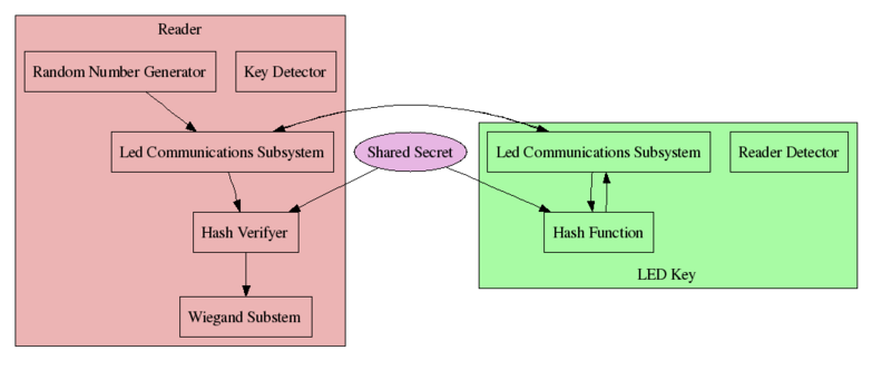
When the reader comes up, it initializes the LED Communications subsystem (LEDComm), and waits for a key to come into range. When the key comes into view, it attempts to perform a clock synchronization. If the two devices can sync, then we have a channel over which data can be sent serially. The reader then issues a challenge by sending an encrypted random number for the key to process, and waits for the key to return a response to the challenge. The key computes the response by decrypting the encrypted random number, adding its key-id to the number, and then re-encrypting the modified number. This encrypted reply is then sent to the reader unit.
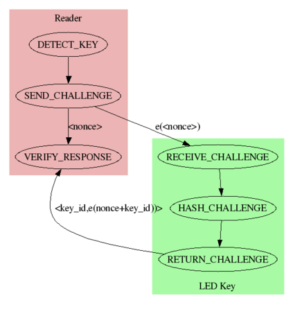
In this way the secret key is never transmitted, but it can be ensured that the key actually knows the key (by simply performing the same computation on the reader and comparing the reply from the key). If they match, then the key is considered to be valid, and the key ID that is provided is sent over the Wiegand protocol to an authenticating server which can then choose to open the door with this information. A state diagram of this transaction is shown below:
The main tradeoff that we made was actually performing the cryptography in software. We used the TEA algorithm, mostly because it was one of the only algorithms that we could fit in the 128 bytes of RAM on the ATTiny2313. There are numerous hardware cryptography chips that could be used to use different cryptographic algorithms; however, we wished to keep extra hardware to a minimum and do all we could in software. Additionally, TEA as implemented is cryptographically secure, so this is not a concern. Moreover, the amount of code necessary to integrate these chips would likely have outweighed their benefits (the Tiny only has 2K of program memory, and does not provide native support for I2C or SPI, so we would likely have had to implement these in software). We believe that choosing a cryptographic algorithm in software is an acceptable solution in this case.
Another point worth nothing is that we do not make any special provision for key storage in this application, we simply rely on the Atmel's EEPROM. In a real application, we would likely want to use a tamper-resistant memory, so that if anyone attempted to extract the shared secret from the device, the memory would be destroyed and the key rendered unreadable. Currently, if one simply reads back the EEPROM, the shared secret can be obtained. Some protection against this can be obtained by setting the appropriate ATmega memory lock bits.
We did not find any standards directly related to the implementation of communication over the LED; however, the scheme that we used was identical to that described by the MERL researchers. It is essentially highly similar to 8-N-1 RS232; however it is half-duplex (each unit takes a turn to send one bit), and MARK and SPACE symbols are sent as pulse-width-modulated light pulses instead of as voltage levels.
To implement communications with an access control system, we implemented the industry-standard Wiegand protocol. The protocol is quite simple, and provides two data lines, one for 1 and one for 0. Both lines are held high by default. The message is sent bitwise by holding the appropriate line low for 5 micro-seconds, followed by holding both lines high for 2ms. The end of a message is indicated by holding both lines up for more than 50ms. A timing diagram is provided below:
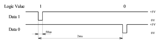
Timing
diagram provided by the Circuit Cellar Article on the Wiegand
Protocol. See references for more information.
This information was taken from a Circuit Cellar article from 2004. We re-implemented this project in C (we did not take anything from the original implementation at all except their description of the Wiegand protocol description), in order to demonstrate that our Wiegand output will be interoperable with current systems. We also tested our reader with existing Wiegand hardware, again to ensure that the output that we produce is 100% compatible with industry standards.
The Wiegand protocol also specifies certain open formats that can be used for interoperability. We chose to implement the 26-bit payload, which is supported by many access control systems. The packet payload looks like:
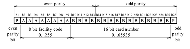
Payload diagram also provided by Circuit Cellar Article. See references.
It should be noted that bits in the packet are sent MSB first, so b2 (the first sent bit in the facility code), actually corresponds to the highest bit in that code. This was one of the important pieces of information that we took away from actually experimenting with Wiegand hardware, as we were unable to ascertain this fact from any of the online documentation that we could find.
For our application we always send a facility code of 1. Each key supports a 16-bit card number.
The Wiegand-Reader hardware that we had to experiment with the Wiegand protocol read original Wiegand-effect cards. It reads 26-bit cards, and also 30-bit cards from Corby, Inc. Marked as "High Security". We were unable to find any documentation online about the format of this card, however we were able to determine the format experimentally. The layout was as follows:
| E | F3 - F0 | S7 - S0 | C15 - C0 | O |
Here F represents a facility code, S represents a "card serial-number" and C represents the card number. The meaning of the serial-number is unknown. The C bits represent the actual card number, however for some reason they seem to be stored (bitwise) inverted on the card, which is curious because the facility bits are stored uninverted. E and O represent even and odd parity bits respectively which, as with the 26-bit payload each are parity for half the message.
In any case, we did everything that we could to ensure that we were in compliance with the Wiegand standard so that our reader was interoperable with current access-control systems.
The research done by Dietz, Yerazunis, and Midgal (the authors of the MERL paper from which we took our inspiration) was awarded U.S. Patent 6,870,148 ("LED with controlled capacitive discharge for photo sensing") on March 22, 2005. If our project was productized, this work would have to be licensed under some terms.
We do not know of any other concerns that would apply to this project. The Wiegand protocol is an open industry standard and has no IP protection that we can find, despite an extensive search. The cryptographic algorithm that we have utilized (Wheeler and Needham's TEA algorithm) is unencumbered.
Project Design | [ top ] |
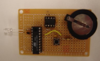
The system consists of a reader unit and a key unit. We also built a Wiegand protocol decoder, but this was only to demonstrate that our system is functioning correctly, so it is not factored into our budget (Professor Land said this was fine). We had originally planned to implement the key on an ATTiny2313 (and a custom board, pictured below); however, we were forced to change our plans at the last minute when we discovered that we could not get the final revision of our code down to below 2K (the size of the program flash memory on the Tiny2313). Up until the day before the project was due, our code was below 2K, but the final day we had to make changes that made the code-size go up to 2150 bytes, and we were unable to reclaim any space to make the key run on the Tiny. Unfortunately we were unable to order a small micro-controller which would have satisfied our needs (the ATTiny44, 84 or 85 would have been quite sufficient) in time for the project deadline. Luckily, our budget had plenty of slack, so we simply chose to use another Bruce-Land-board with an ATMega32 on it for demonstration purposes.
One of the most pressing issues in the design of the key was choosing a micro-controller with a low power consumption to facilitate a long battery life. We also did not require a fully featured micro, such as the ATmega32, as the key's purpose was to send and receive data via LED and to turn on at the push of a button, requiring just three general purpose I/O pins. We chose the ATtiny2313 because it had the lowest power consumption of all the microcontrollers we looked at from Atmel, it came in a 20-pin package, affording us a few extra pins in case we wanted to add more to the chip, and it was cheap coming in at just over $2.
Powering the key are two powerful lithium ion coin cell batteries. These 3v, 250mAh batteries were chosen for their small footprint, long life and power. The batteries are placed in series on their holder, and the 6v supply voltage generated is fed into a Texas Instruments TPS7250 low-dropoff voltage (LDO) regulator, which in turn produces the 5v supply that is fed to the ATtiny. A LDO was chosen over a regular regulator because of the 1 volt difference between the supply from the batteries and the supply from the regulator. The most common regulators require a difference of 1.5v between input and output voltages to provide a steady output, and this is something that is simply not possible with our current setup. The LDO is connected on the key as follows:
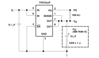 Wiring diagram provided by the Texas Instruments datasheet.
While the LDO requires a little more wiring, it has a rather small footprint, and thus does not matter too much. The LDO works fine with our batteries, and we have always observed a very steady 5v output voltage from it. To prevent any high frequency noise from entering the system, 0.1�F decoupling capacitors are placed between the positive and negative supply terminals both pre and post LDO.
The ATtiny itself only has three GPIO pins used. PORTB.0 and PORTB.1 are used to power the LED for communication, with the LED hooked up to a 75 ohm resistor in order to provide for extra brightness. There is a pull down switch connected to the INT0 pin to wake the micro-controller up from sleep and to turn on the LED. A pull down is used as it is a requirement of the micro-controller. Below is a schematic of the ATtiny, with the power coming from the LDO:
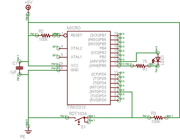
We utilize the internal oscillator on the ATtiny to reduce clutter on the board.
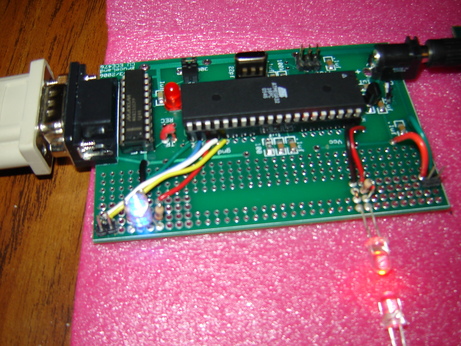
Key-board as demonstrated, but with several debugging leads attached.
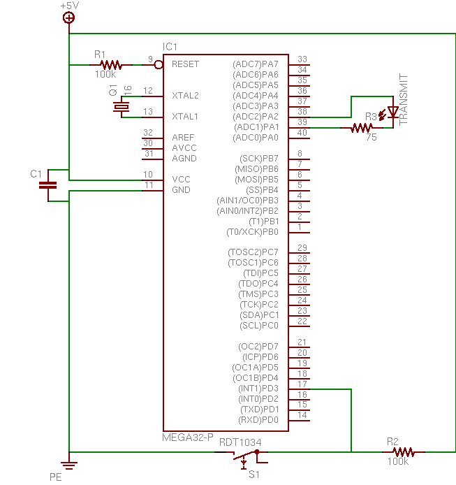
Again, we were unfortunately unable to use this board for the final demonstration (though we did have our entire LED communications suite running on it successfully) because of the aforementioned size problem. Instead we used another project board. The new key is wired up in the same way as the ATtiny key-- there is a pull down switch attached to the INT1 pin to allow wake from sleep and start transmit, and the LED is hooked up in the exact same way as on the Tiny. We used an external crystal for this board as there was already an allocated spot, and we were not concerned with taking up space. It was unnecessary to use an LDO regulator for this board as it is powered by a 9v battery, ensuring proper operation of the on-board regulator. One advantage the Bruce Land ECE476 board has over our custom made ATtiny board was the ability to reprogram the chip in-circuit. While in a production setting in circuit programming is next to useless for a key, for our proof-of-concept it is extremely helpful in allowing us to make changes to our code quickly. Below is a circuit schematic of the ATmega32 key with power and ground being supplied by the onboard voltage regulator:
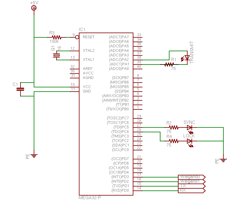
The base for the lock is based on Bruce Land's ECE476 ATmega32 board. Serial capability was enabled for debugging purposes, so a MAX233 was soldered in. Added to this board were three LEDs-- one for transmission of data, one to indicate the status of the lock (on for open, off for locked), and one to indicate that the key and lock are communicating (to aid in the aiming of the LED). Wiegand outputs are direct connections from the microcontrollers pins, though if we had a bigger board available, these may connect to screw-terminals for ease of use. Below is a shcematic of our base board, with power and ground being supplied by the onboard voltage regulator:
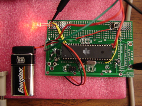
A picture of the final board:
We suspect many readers are surprised to learn that LEDs can be used to sense light as well as emit it. This is not news -- the phenomenon was first noted by Forrest Mims in the '70s; the MERL researchers reference his original work in the area in their paper.
The procedure we use for sensing light with an LED is simple. We fix our light measurement duration at 100 microseconds. At the start of the interval, we reverse-bias the LED by applying +5 volts to its cathode and 0V to its anode. We then set the microcontroller pin connected to the anode as an input pin with no pullup. An LED operated as such can be modeled as a small capacitance in parallel with a current source (photocurrent from the light incident upon the LED). As incident light increases, the capacitance discharges (approximately) proportionally.
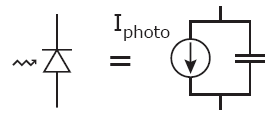
Model of an LED as a photosensor. Reproduced
from MERL technical report 2003-35 (see bibliography).
All of our software was designed using avr-gcc and avr-libc rather than the CodeVision compiler that we utilized for the rest of the class. We made this decision primarily because we wanted to experiment with avr-gcc and the open source avr tools (uisp, avr-binutils, etc.). We found gcc-avr to be quite capable. Unlike CodeVision, it is a true compiler/linker, so while CodeVision simply appends all of the files in a project together, avr-gcc creates object files and then links them. This was very important as it different people to work on different parts of the project with carefully defined interfaces. The fact that each person could work on their own object files allowed for overlapping names (for static variables), overlapping pre-processor definitions, etc. From a software-engineering perspective, this was a huge advantage.
There were very few differences in terms of the actual API provided by avr-libc versus the CodeVision API. The most major difference is that, to use the I/O functions you need to define your own functions to interact with the UART (for maximum generality and to accommodate the larger Megas which have more than one UART). We found this very useful and constructed a buffered writer which could be used from within interrupts and time-critical sections to still output debugging information.
Also, gcc-avr does not support the 0b extension for writing out binary numbers. This meant that to set specific bits, we needed to define macros (set_bit and unset_bit), which was made possible by the fact that gcc-avr actually supports full macro-expansion. Avr-libc also provides definitions for each bit of each field on the AVR, so it is possible to set bits with their name rather than simply inserting magic numbers. All in all, we feel that these changes were ultimately positive because they forced us to produce more understandable code.
In order to delegate the software development responsibilities for the project, we made sure to specify a clear interface to the led communications subsystem before getting deeply involved in coding around it. The following functions were implemented to allow interaction with the rest of the system.
#include <stdint.h>

// Maximum length of a single message
#define LEDCOMM_MAXRXBUF 30

/* Call once and only once, and before any of the LEDcomm functions */
void ledcomm_init();

/* Returns 1 if we are synchronized with another LEDcomm unit, 0 otherwise.
   Not blocking. */
uint8_t ledcomm_client_present();

/* Returns the number of bytes currently in the LEDcomm RX buffer */
uint8_t ledcomm_rx_len();
/* Returns location of the LEDcomm RX buffer */
char* ledcomm_get_rxbuf();
/* Clears the LEDcomm RX buffer */
void ledcomm_rx_reset();

/* Transmits nbytes bytes from the buf buffer over the LEDcomm interface
   Returns 1 for all bytes TX'd, or -1 for error.  Blocks. */
int8_t ledcomm_send_buffer(char *buf, uint8_t nbytes);

/* Shuts down the LEDcomm subsystem (including depowering LED)
   or restarts it */
void ledcomm_sleep();
void ledcomm_unsleep();

/* This needs to be called every 100 microseconds from an
 * interrupt for the ledcomm subsystem to work */
void ledcomm_tick();
This encapsulation means that this code can be reused easily
in any project. Before sending ledcomm_init must
be called, and an interrupt handler must be setup which calls
ledcomm_tick every 100 microseconds. We chose to separate
this functionality out so that applications could call ledcomm_tick
in a way that is convenient for them, while still being able to use
the timer for other time-specific issues. To receive, the client
must wait for ledcomm_client_present to be non-zero.
This indicates that a client is on the other end of the LED connection,
and that the clocks have been synced. The client can then perform
ledcomm_send_buffer, which sends the client data, or wait
for ledcomm_rx_len to be a specific length. The receive
buffer can be accessed directly with ledcomm_rx_buf and it
is not circular: the buffer is written into until it is full and then
data is discarded. When the client is done with the data in the buffer,
he must called ledcomm_rx_reset. This design, though a
bit simplistic for some applications was chosen to accommodate the Tiny
(which only has 128 bytes of ram and a very limited program memory)
when we thought we were going to be using it.
The LEDcomm protocol is ran by a state machine with two states. The first state is the discover state. In this state, LEDcomm devices beacon by transmitting for 1ms, and then receive for 4ms, looking for the beacon of another device. If they receive another device's beacon within that time period, they go from the discover state to the synchronize state.
In the synchronize state, we wait 1ms, we transmit, and then go into a receive cycle where we instead look for the falling edge of a light pulse from another unit, with a maximum receive cycle duration of 4ms. A falling edge is defined as seeing, in the past ten light measurements, two consecutive measurements of light-seen, and eight consecutive measurements of light-not-seen. The reception of a falling edge allows the receiving unit to determine the clock phase of the transmitting unit. Upon receiving a falling edge, we stop our receive cycle and go into the wait-before-transmit state, effectively synchronizing our transmit cycle to be almost exactly out of phase with the other unit's transmit cycle (and thus, in the middle of that unit's receive window).
Data transfer is performed by pulse-width-modulation of the bits transmitted. It is the exact same software as the synchronize loop. Similar to conventions used in RS232, if we have no data to transmit, we transmit a MARK (a 1ms pulse, which we equate to a logic level 1). Data is transmitted a byte at a time in frames. The beginning of a frame is marked by a SPACE (0.5ms pulse, equated to a logic level 0) being transmitted. The bits in the byte are then transmitted least-significant-bit first, and the end of the frame is signalled with another MARK bit. The transmitter may then return to the idle state of sending MARKs continuously, or may instead immediately transmit another SPACE to signal the start of another character frame.
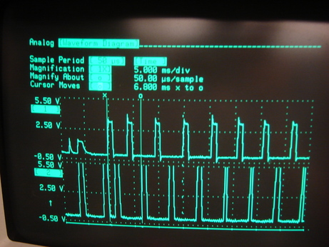
Below we show an oscilloscope trace of two units synchronizing with each other. Unit 2 (on the bottom trace) is idling in the discovery state, beaconing for 1ms every 4ms. Unit 1 is turned on and sends its first beacon at the location of the "x" cursor (the first vertical line through the entire plot). After Unit 1's second beacon, Unit 2 finds the falling edge of Unit 1's pulse, and synchronizes its clock (this is visible at the location of the "o" cursor). The two units are now capable of data transfer.
A highlevel view of the state machine of the reader is shown below.
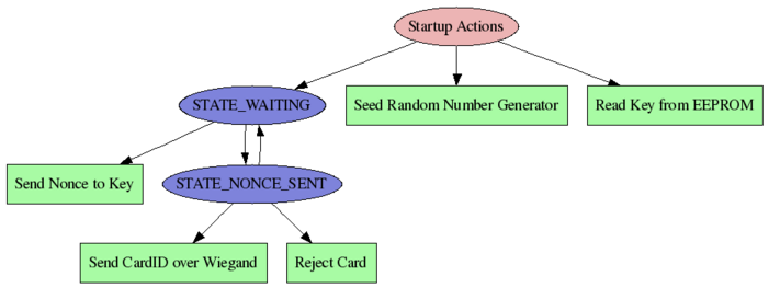
When the reader first starts up, it retrieves the key from EEPROM, and
seeds the random number generator off of the (unconnected and thus
floating) ADC. We found that capturing the bottom two bits off the
ADC gives very good randomness. The code to do this is found in the
random_initialize function.
Once the system finishes these startup actions, it enters STATE_WAITING, where it simply waits to sync with another LED device. When a device can be found, it generates a random one-time number (known as a nonce), which it proceeds to encrpyt with its key. It sends this to the reader and waits for a response. If the response confirms that they have the same shared secret, only then is the card ID actually transmitted over Wiegand so that it can access can be granted farther upstream by an access control server.
The design of the key is much the same as the reader. It was designed to run on the AtTiny, so the entire code-base is just over 2k-bytes when compiled and uses less than 128-bytes of RAM. A state machine is shown below which depicts the basic functioning.
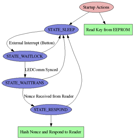
In order to minimize power consumption but also provide an intuitive user interface, we have put a pushbutton on the outside of the device (this also prevents the device from being read without the users knowledge). The device spends most of its time in the Power-Down sleep mode. It is woken from this sleep mode by an external interrupt that comes from the level change resulting from a button press. In a commercial application a capacitance sensor could be used to determine when it was in the hand of a person, and use this to wake the processor from its sleep mode.
Once the processor has been woken from its sleep state, it attempts to perform a serial synchronization with the LEDComm interface. If serial cannot be synced within on second, then the device goes back into sleep mode. Once communications has been established, the key waits for a nonce to be transmitted. Again, if it received nothing within a second, it returns to sleep mode. Upon receiving the nonce it is hashed, and returned to the reader along with the key ID. Also, the key ID is combined with the data before it is hashed, to prevent the possibility of someone intercepting the packet and replacing the key ID which is embedded in it.
When this entire transaction is concluded the key returns to sleep mode.
Results | [ top ] |
We were able to get a throughput of 250 bits/second. We were able to get slightly faster speeds, however we traded off accuracy. Thus, we found that this speed more than satisfactory for our purposes.
We can acheive 90% accuracy in terms of messages successfully transmitted. This puts our per bit accuracy at well over 99% thought we have not actually measured it.
We have done our best to assure that the product was safe. We have provided the best security that we could, but have also tried to pay attention to physical safety. If this product was actually used it would require an enclosure for the reader to assure that no one had access to the device internals, and thus could not injure themselves. Given a safe enclosure, we believe the device to be quite safe for prolonged use.
We have tried to do our best to ensure that the device is secure. We hope that the above sections about our cryptographic protocol were satisfying in that respect. One note: currently the key is simply stored on the device's EEPROM. In a real application, the key would be stored on a tamper-resistant external storage device, such that if anyone attempted to extract the key from the device, it would be destroyed.
We have found the device to be quite resistant to ambient light, so we are able to handle a large amount of interference and still function correctly. In terms of interference emitted, we are not using anything that is explicitly in the RF spectrum. As such, we do not believe that we are emitting any more interference than any other non RF project.
Our device has a very simple user interface: it consists only of a single button on the key. It can be difficult to line the key up with the reader, but a good enclosure could aid greatly in this task. It should be noted that our project is not as usable as some other access control systems from people with impairments: RFID tags will read if the person just bumps the reader with the tag in their pocket. Nonetheless, we have done the best to make the system usable, and we believe that the glaring red led is an invitation to use the product.
Conclusions | [ top ] |
At the onset of the project, we had hoped to build a bidirectional communication protocol utilizing LEDs as the channel. We successfully attained this goal through some trial and error, both with hardware and with software. We found that it is very important for the LEDs used in any communication to have clear lenses, otherwise the filtering effects of a diffused or colored lens will impact the performance. Our secondary goal was to have a secure channel of communication. To reach this, we utilized the TEA encryption algorithm and found it to be acceptably secure while consuming relatively few system resources. As the project progressed, we thought of adding maintenance features to the base (such as a serial interface) and expandability features (multiple keys stored on the lock). Unfortunately, we were not able to reach these goals due to time constraints and problems with using the EEPROM. Also, we failed in being able to use a smaller, lightweight microcontroller for a key due to it's lack of memory. Overall, however, we were able to make the most important parts of our project work well, and find our work to be a successful proof of concept design.
We have made every attempt to follow standards where relevant. We have made every attempt to ensure that when we did follow standards (i.e. Wiegand), we validated that our implementation was interoperable with current work.
We have tried to acknowledge the work of others, and we have pointed out potential issues with bringing this product to market (the existence of a U.S. patent on some of the technology used). To our knowledge, none of the other technology that we have used is patent encumbered. We did use code that was in the public domain with our TEA implementation. We did reverse engineer the Wiegand protocol used by the Corby card reader (the 30-bit format). This was only to test that our Wiegand implementation functioned properly. It is not directly relevant to the product, so we do not believe that their are any intellectual property considerations.
We attempted to conduct ourselves in accordance with both the letter and the spirit of the IEEE code of ethics.
We do not anticipate any legal considerations, as we are not transmitting over air or performing any task regulated by a government body. It seems likely that we could have legal liability if a malfunctioning lock led to a compromise of a facility, but this is to be expected with any product in this space.
References | [ top ] |
Datasheet
Articles
Appendix A: Program Listing | [ top ] |
Full code can be downloaded from here.
Appendix B: Schematics | [ top ] |
Schematics have been included in the section on Hardware design.
Appendix C: Cost Details | [ top ] |
| Quantity | Item | Unit Price | Extension |
| 2 | Bruce-Land Board | $5.00 | $10.00 |
| 1 | Serial Setup (Connector + MAX233) | $8.00 | $8.00 |
| 2 | ATMega32 | $8.00 | $16.00 |
| 2 | Bright Red LED | $0.50 | $1.00 |
| 1 | 12V Power Supply | $5.00 | $5.00 |
| 1 | 9V Battery | $2.00 | $2.00 |
| 1 | Tri-Color LED | $1.50 | $1.50 |
| 1 | Push-Button Switch | $.20 | $.20 |
| n/a | Various Resistors | In-Lab | $0 |
Total: | $43.70 | ||
Appendix D: Team Member Responsibilities | [ top ] |